This thread has been locked.

If you have a related question, please click the "Ask a related question" button in the top right corner. The newly created question will be automatically linked to this question.

CCS/CC2650: as master for I2C communication with PN532 RFID module

Other Parts Discussed in Thread: CC2650, CC2640R2F, CC2640, CC2650STK

rt Number: CC2650

Tool/software: Code Composer Studio

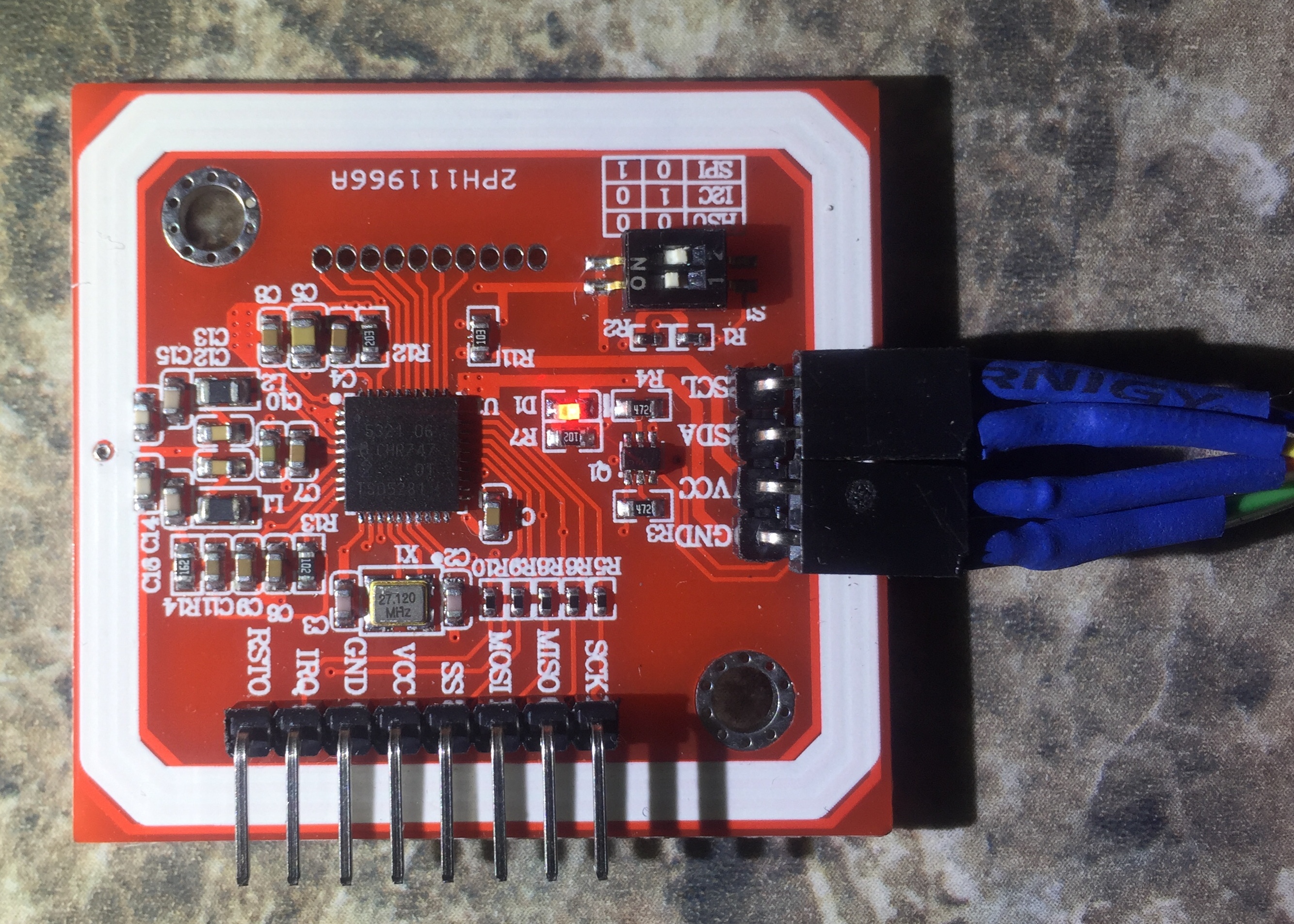
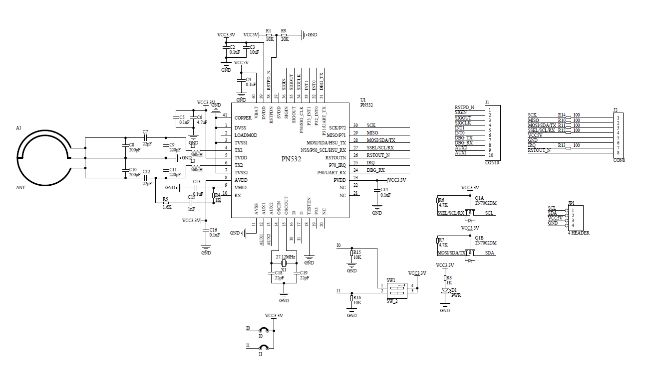
I have a need to do I2C communications with an existing Elechouse RFID reader module that uses an NXP PN532.

After reading the 530 pages of PN532 datasheet, user manual, application note and Elechouse PN532 NFC RFID Module User Guide Version 3, I failed miserably to even get a response from the PN532 module.

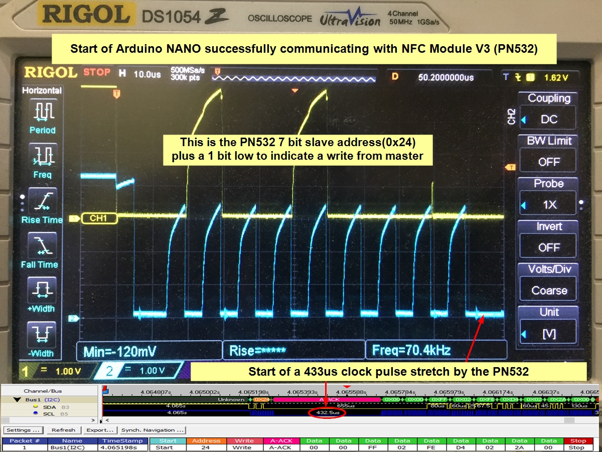
I then resorted to grabbing an Arduino Nano I had kicking around and used Elechouse Arduino library examples to get the module to successfully read my Mifare 1k tag's Uid.

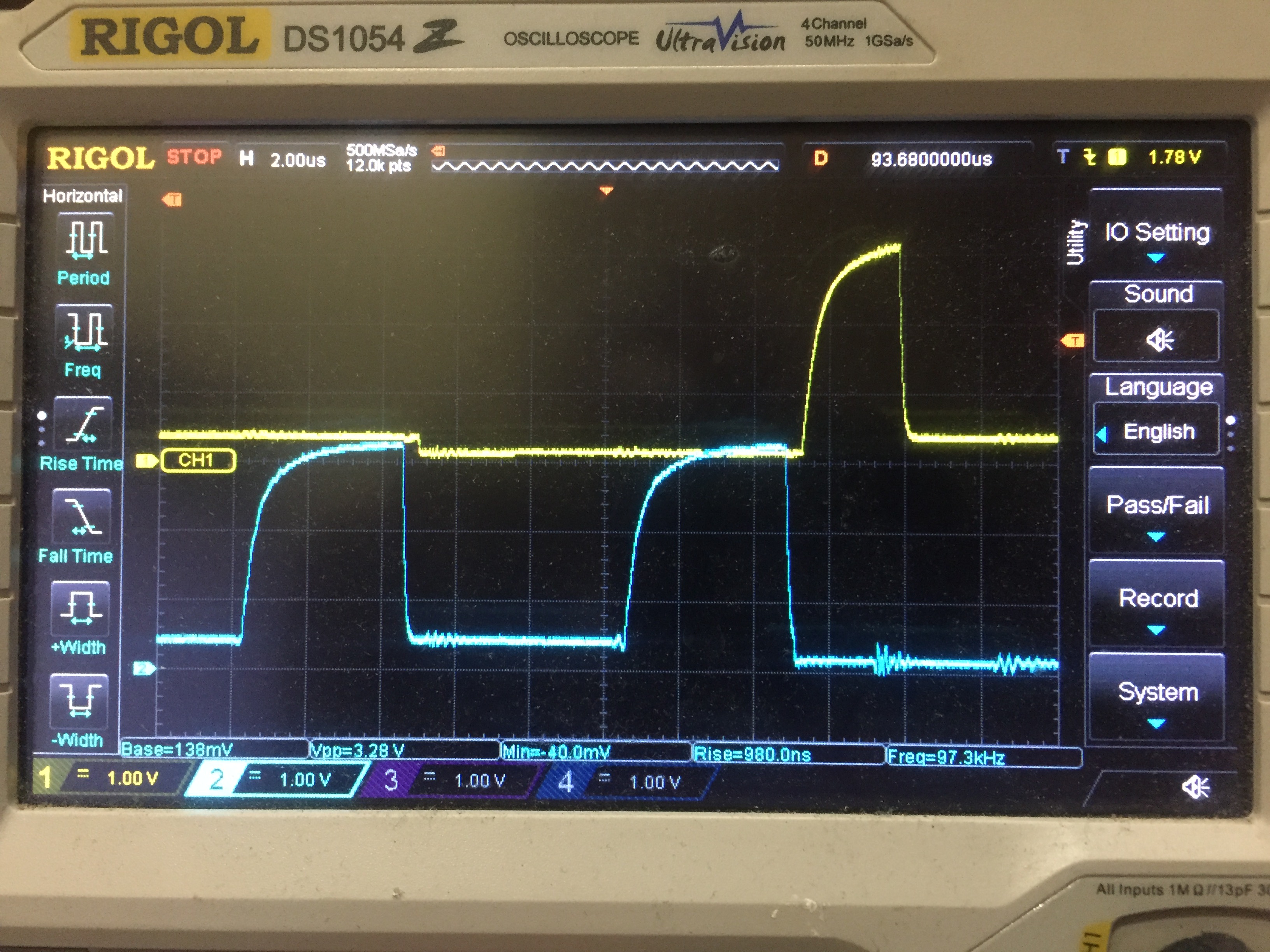
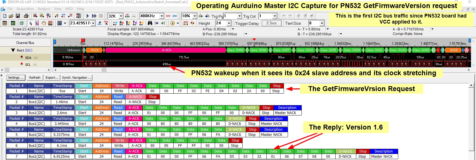
I then used my Logic analyzer to capture the I2C bus traffic when the Arduino sketch started up.

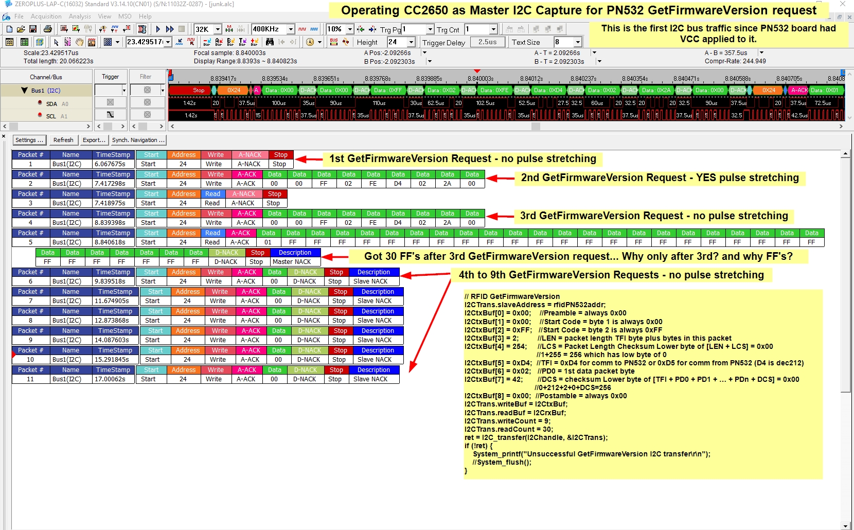
That gives me a map of what I2C commands I need to mirror in my 'CC2650 as master' code and here is the first command and response that 'Arduino as master' does after the PN532 has power applied to it. (GetFirmWareVersion):

Then, I tried to match that communication traffic with the CC2650 and I could only get this far (my code is in the image):

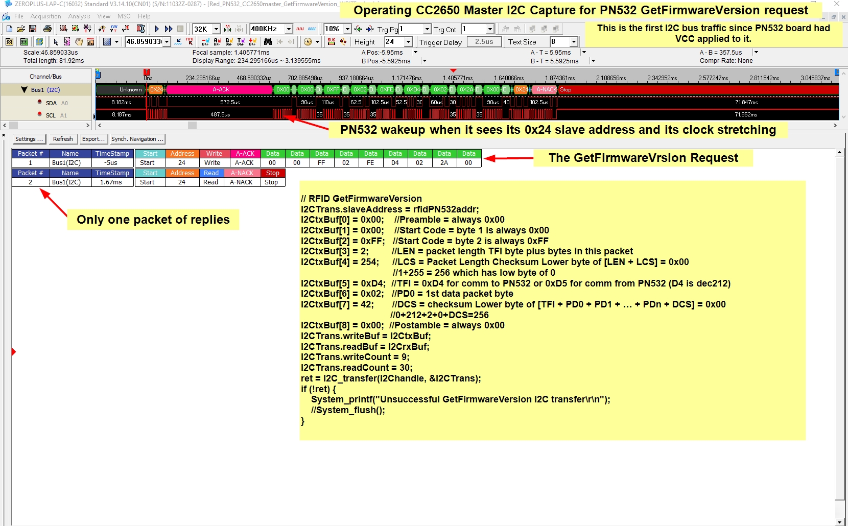
So, the only thing I have accomplished so far is to wakeup the PN532 by sending its slave address of 0x24 on the I2C bus and then it clock stretches while it stretches its legs I guess ;).

I can not figure out how to read its full response to my GetFirmwareVersion request like the Arduino is able to.

Can anyone give me some guidance on how to obtain the complete set of responses to my GetFirmwareVersion request with 'CC2650 as master'  that 'Arduino as master' is getting from the PN532 module?

Once I can get the full responses to this request, I am pretty sure that I can continue form there to completion of my code.

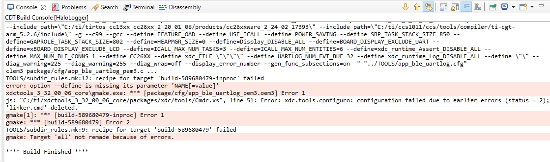
And, by the way, my I2C_transfer command fails because I get my console message of "Unsuccessful GetFirmwareVersion I2C transfer".

Thanks,

Dale

  • And even more oddities.

    I put my code into a periodic event that fires normally every second (not sure why it is not a consistent 1 sec here) and captured the I2C traffic for 9 GetFirmwareVersion requests.

    Here are the strange results:

    Could this strange behavior be caused by the fact that the I2C_transfer function returns an error condition for each request?

  • Hi Dale,

    Bearing in mind that I don't know anything about the RFID module, what is its operating voltage and is it supplied by the master device?  Also, are the I2C pull-up resistors the exact same for the CC2650 as with the Arduino?  And have you tried using two different I2C transfers for write/read operations?  Please refer to the I2C TI Driver API reference for more usage examples.

    Regards,
    Ryan

  • Hi Ryan,

    I am using 1k pullups and here are my clock and data lines at 400khz I2C bus frequency (all the data presented so far was at a 100khz I2C bus frequency), so I think we can rule bus rise/fall time and voltage issues:

    The RFID is running on 3.3v, the same as the CC2650.

    And, yes I have tried using two different I2C transfers for write/read operations by using the I2C_transfer() function with either I2Ctrans.readCount 0  for a write only and I2Ctrans.writeCount = 0 for a read only.  The results are even more confusing than what I have presented so far.  There must be something deep in the bowels of the 500 pages of NXP documents that I have overlooked, which is quite easy for a newbie like me to do.

    Datasheet: https://www.nxp.com/docs/en/nxp/data-sheets/PN532_C1.pdf

    User Manual: https://www.nxp.com/docs/en/user-guide/141520.pdf

    Application Note: https://www.nxp.com/docs/en/nxp/application-notes/AN133910.pdf

    Elechouse PN532 NFC RFID Module User Guide Version 3: http://www.elechouse.com/elechouse/images/product/PN532_module_V3/PN532_%20Manual_V3.pdf

    I am able to successfully communicate with a BME280 I2C temperature/humidity sensor but there seems to be a special trick that eludes me for this NXP PN532 RFID module:

    I have been using your referenced TI Driver API reference and that specific I2C library using this include file '#include <ti/drivers/I2C.h>'

    Any other help would be appreciated.

    Dale

    EDIT: Perhaps I need to use semaphore handles for multiple transaction but the full code commands to achieve that is beyond me.  Can someone suggest a code snippet to try using semaphores?

  • Just to be safe on voltage levels, I decided to go with 2k pullups on a 100khz bus, but the issues persist.

    I find it interesting that this is a shot of the first address byte of the PN532, after which I expect that the PN532 should pulse stretch the clock line.

    We can see the PN532 starting the clock stretching and it is able to bring the clock line down to almost 0 volts, while the CC25650 can not seem bring the voltage so close to 0.  We also see a data bit from the PN532 which is very narrow, does anyone have any idea why the bit is so narrow and does it matter being so narrow (just reaching at straws right now ;) )  

    THIS IS CC2650 as MASTER and it is the start of a failed communication with the PN532:

  • If you are able to get the Arduino working with the NXP PN532 RFID module and a CC2650 to control the BME280 temp/humidity sensor, I suspect a voltage incompatibility issue.  What information I can find of the module mentions "On-board level shifter, standard 5V TTL for I2C and UART, 3.3V TTL SPI" (here's another link).  Have you considered contacting the manufacturers or referencing similar E2E posts?

    Regards,
    Ryan

  • Wouldn't the fact that the PN532 is pulse stretching the clock indicate that it is happy with the I2C bus logic levels because it is able to see its slave address as sent from the CCC2650 using 3.3v logic levels (in this particular case we see that the CC2650 sent out Highs at 3.5v and Lows at about 0.5v)?

    EDIT: We do not see any 5v bits from the PN532, just a narrow bit that looks to approach 3.5v which is below the 4.1v max voltage limit on any CC2650 digital input pin.

    EDIT: Also with regard to the 'On-board level shifter, standard 5V TTL for I2C and UART, 3.3V TTL SPI', here is what I believe is the schematic for the PN532 module and I don't see any level shifters on SDA and SCL I2C pins.  Also, I see why they are able to drive the lines so low since they use a couple 2N7002's to drive them. Also the PN532 datasheet makes no mention of a level shifter on the I2C lines:

  • Thanks for providing further details, I understand your perspective and the I2C signals appear clean.  As I have no experience with the PN532 I am attempting to account for any possible discrepancies.  If you've been able to replicate the stop bit at the end of the GetFirmwardVersion Request then the commands would be nearly identical except for the voltage level.  Have you corresponded with the NXP forum as well for their perspective on the matter?

    Regards,
    Ryan

  • NEW INFO:

    I have captured the start of the 'Arduino as master' successful communication with the PN532 on a 100khz bus.

    WOW, I didn't know the I2C bus was so compliant with poorly shaped bus pulses, the Arduino goes on after this to initialize the PN532 and reads the Uid of a Mifare 1k tag...

    Not sure there is an almost non existent 'narrow PN532 data pulse' after clock pulse 8 and with the CC2650, the wider 'narrow PN532 data pulse' is after clock pulse 9:

  • Ryan asked "Have you corresponded with the NXP forum as well for their perspective on the matter?"

    Not yet since I am still considering the issue to be with the I2C library (or my use of the library) to be the issue.  At some point I will likely ask them, after I confirm that it might be NXP issue.

    Ryan stated 'If you've been able to replicate the stop bit at the end of the GetFirmwardVersion Request then the commands would be nearly identical except for the voltage level.'

    I have not been able to understand that sometime the logic analyzer sees a stop bit at the end and sometimes it does not.

    Sorry, I have not found any 'quoting' ability in this forum interface yet, is there?

  • Sorry for clicking "TI Thinks Resolved", you can reject as an answer if you want...

    Dale Kramer said:
    Sorry, I have not found any 'quoting' ability in this forum interface yet, is there?

    The "Quote" button is available to the right of "Cancel" after clicking "Reply" to start a response, you simply highlight the text you want before pressing the button to create the quote text.

    Regards,
    Ryan

  • Ryan Brown1 said:
    The "Quote" button is available to the right of "Cancel" after clicking "Reply"

    Ah, yes and sometimes I don't see the forest for the trees too ;)

    I guess I should have tried markup syntax too.

  • I decided to try to get some NXP help and started a topic there, pointing to this topic here.

    I hope that I am forgiven there for doing that...

    Here is that topic.

  • FURTHER INFO:

    I have looked beyond the first byte of transmission and here is a summary of current status of my issue:

    There seems to be a mystery pulse in the CC2650 as Master data stream and I can not figure whether the PN532 is generating it or the CC2650 is, whether this mystery pulse is the reason that the PN532 stops listening after the pulse with the CC2650 as Master and whether the mystery pulse is responsible for the HUGE clock stretching that occurs with the CC2650 as Master.

    Here is the I2C bus data for successful Arduino vs failed CC2650:

  • To me it looks like the CC2650 creates the mystery pulse, here is my reasoning.

    1. Both the CC2650 and the PN532 pull the I2C lines to a different LOW voltage level.  The PN532 pulls low to ~0.2v (due to 2N7002 mosfet drivers on the PN532 module board) and the CC2650 only pulls lows down to 0.7v.
    2. After the 8th clock cycle from the CC2650 when it has sent the PN532 slave address, the PN532 sends an ACK on the data line and is confirmed by the fact that the data line is pulled down to ~0.2v about 0.4us after the clock line reaches a low value after the 8th clock bit.
    3. The CC2650 then provides a 9th clock cycle before the PN532 starts to clock stretch at about 1us after the clock line reaches a low value after the 9th clock bit (you can see the clock stretching initiated by the PN532 since it brings the clock line down to ~0.2v at that point.
    4. Now along comes the 0.2us wide mystery pulse on the data line about 0.4us after the 9th clock bit is brought low by the CC2650, but who created it?.  
    5. Since the clock is low at this point, I think the I2C spec allows either master or slave for legally operate the data line, but I think we can conclude that the source of the mystery pulse is the CC2650 since the mystery pulse returns to the 0.7v of a CC2650 low value.

    Here is a zoomed in view of the 8th and 9th clock bits and the 2us wide mystery data pulse:

    Is my reasoning correct so far?

    EDIT: On second thought I think it must be the PN532 since the Mystery data pulse is starting from the PN532 low level of 0.2v....

    HELP ... Who makes the mystery data pulse ???

    They both must simultaneously let go of the data line for it to go high and then the CC2650 must bring it low again since it only comes down to 0.7v.

    THEORY: Since the next data byte that the CC2650 is trying to send after the clock stretching is 0x00, then perhaps the CC2650 should not have released the low on the data line.  Especially if this is what may be confusing the PN532.

    LOL, this is so confusing, am I even in the correct rabbit hole?  :)

  • Hi Dale,

    In regards to the pulse on the SDA line, I agree that both the master and slave have released it after the slave ACK and before the master regains control.  During this time neither controls the line and it's pulled high by the mandatory pull-up resistors.  This is perfectly fine as the SCL line is low and SDA is only sampled when SCL is high.  This should not affect I2C communication according to the protocol and I don't know why the PN532 logic would be concerned over this.

    Regards,
    Ryan

  • Why does the CC2650 let go of the SDA line after the 9th clock bit when it knows the next data bit which it sends will be a LOW?

    It doesn't even know that the PN532 is clock stretching at the time that the CC2650 lets go of SDA after the 9th clock bit, does it? So why let go?

  • It let go after the 8th clock bit so that the PN532 could ACK on the 9th, and only regains control after the observed pulse.  As stated previously the delay in doing so should be inconsequential given the status of the SCL line and I2C protocol.  I suspect the same behavior is evident in the working BME280.  You can ask the NXP forum as to why this may be a concern for the PN532.  You could also consider further optimizing the pull-up resistance to address the pull-down voltage level difference.

    Regards,
    Ryan

  • Dale Kramer said:
    The PN532 pulls low to ~0.2v (due to 2N7002 mosfet drivers on the PN532 module board) and the CC2650 only pulls lows down to 0.7v.

    The DC Characteristics section of the CC2650 datasheet has:

    If the CC2650 can only pull down to 0.7V maybe the CC2650 doesn't recognise the correct bus state, due to not meeting the VIL specification.

    As Ryan has suggested, changing the pull-up resistors on the CC2650 side could help to meet the VIL specification.

  • Hi Chester,

    I have been concerned about the energy draw of the CC2650 I2C commands, I have 3 slave devices on the bus and each of them so far always respond to the data and clock pulses from the CC2650 properly as Highs and Lows with my 2k pullups.

    The data I am getting back from each of the slave I2C devices for Lows has been less than the 0.2 volts you specify so the CC2650 should have no problem with interpreting data received from them.

    I have tried 1k pullups when trying this PN532 request and the problem persisted.

    Perhaps I will try 500 ohm pullups and see if that helps but I do not expect it to.

    Is my logic about conserving energy with CC2650 commands on the bus solid? (After all this is a battery powered device).

  • Dale Kramer said:
    Perhaps I will try 500 ohm pullups and see if that helps but I do not expect it to.

    To reduce the current drain and the 'low' voltage, don't you need need higher value pull-up resistors?

    Say 4.7K.

  • Yes, but to test fully that you think my current issue with PN532 may be due to the 0.7v lows with 2k, I should try <0.2v with 500 ohm.

    If that is what it takes then I will bite the bullet on energy consumption and leave the 500 ohm resistors in place ;)

  • Hi Dale,

    I agree with Chester, your I2C pull-up resistors of 1K and 2K Ohm resistors is too low. Normally I2C pull-up resistors value is 4.7K Ohm. You need to make sure the I2C communication works first between C2650 and PN532. Then worry about the current consumption. The current draw is caused by I2C line is from the PN532 circuitry.

    The PN532 should have Arduino Code Library which you can port to work for CC2650.

    Also, I suggest you to use CC2640R2F instead of CC2650.

    -kel

  • Hi kel

    Sorry guys I was thinking about how to get a faster rise time (I was thinking of using a higher bus speed).

    Even without any pullups on CLK and SDA the rise time is still only 0.3 us to get from Low to 2v which is faster than the Arduino which can communicate with PN532 just fine.

    But the Low level without pullups with the CC2650 (actually a 2640F128 but that should be no issue here) is still ~360mv, not sure how to get it to less than 200 mv...

    I have looked at the Arduino code and it is not in my capabilities to port the code over to CCS, that is why I am trying to match the bus signals using our I2C.h library.

    I wish that I were using the 2640R2F but it in not a possibility right now.  I have to work with the 1000s of CC2640F128's that we have delivered in the last 3 or 4 years.

    HERE IS THE MYSTERY PULSE WITH NO PULLUPS:

    Looking back at the successful data on the bus when the Arduino is master, there is just no mystery pulse. I am getting no response from the NXP forum topic, maybe they will respond after their holidays.

    You guys are great here guiding my ramblings throughout the holidays :)

    Happy New Year!

  • Hi Dale,

    If you are using the Elechouse PN532 module the pull up resistor is already installed so should not be a problem. Your issue is implementing CC2640 I2C Code to communicate with the Elechouse PN532 module. I have ported Arduino Code Libraries to work for TI BLE MCU's and it's not easy but doable. Anyway, if you are unable to port Arduino PN532 then ask help from someone who can. You need to implement the code then best to capture the I2C communication using Logic Analyzer.

  • OK ;) HELP, I do not have the skills to port over working Arduino code here. (Is there anywhere else I should ask for help?)

    I started this topic showing my logic analyzer captures but dug deeper when I wanted to see the source data with my scope.  I am now capturing simultaneously on both the scope and logic analyzer so all bases should be covered.

  • Looking back the LSA captures on the first post:

    a. The GetFirmwareVersionRequest from the Arduino ends with a STOP.

    b. The GetFirmwareVersionRequest from the CC2650 doesn't contain a STOP.

    The code fragment for the CC2650 I2C master has:

    I2CTrans.writeCount = 9;
    I2CTrans.readCount = 30;
    ret = I2CTransfer (I2CHandle, &I2CTrans);

    I can understand the writeCount of 9 as the number of transmit bytes to transmit in the GetFirmwareVersionRequest.

    However, is the readCount of 30 correct in this case?

    If the readCount is zero for the GetFirmwareVersionRequest, does that cause a STOP to be sent by the CC2650?

    Suspect that the use of I2CTransfer() in the CC2650 code needs to generate the same activity as shown for the working Arduino code.

  • Chester said: 'Suspect that the use of I2CTransfer() in the CC2650 code needs to generate the same activity as shown for the working Arduino code.'

    I agree.

    I have tried all combinations of read/write, write then reads etc and still I don't have the skills to obtain success.  That is what led me to look before the 'missing stop' you have noted and look back to where PN532 does its first NACK (after the clock stretch) and the only differences before that are shown in this image:

    I can't even duplicate the I2C traffic of my first post any more with the same code snippet.  The data in my 2nd post shows the inconsistent I2C bus traffic when I put the code snippet in a periodic loop.  

    The code snippet for the above image is (this is located in an ~1 sec periodic loop):

              // RFID GetFirmwareVersion + read 30 bytes
              I2CTrans.slaveAddress = rfidPN532addr;
              I2CtxBuf[0] = 0x00;  //Preamble = always 0x00
              I2CtxBuf[1] = 0x00;  //Start Code = byte 1 is always 0x00
              I2CtxBuf[2] = 0xFF;  //Start Code = byte 2 is always 0xFF
              I2CtxBuf[3] = 2;     //LEN = packet length TFI byte plus bytes in this packet
              I2CtxBuf[4] = 254;   //LCS = Packet Length Checksum Lower byte of [LEN + LCS] = 0x00
                                 //1+255 = 256 which has low byte of 0
              I2CtxBuf[5] = 0xD4;  //TFI = 0xD4 for comm to PN532 or 0xD5 for comm from PN532 (D4 is dec212)
              I2CtxBuf[6] = 0x02;  //PD0 = 1st data packet byte
              I2CtxBuf[7] = 42;    //DCS = checksum Lower byte of [TFI + PD0 + PD1 + … + PDn + DCS] = 0x00
                                 //0+212+2+0+DCS=256
              I2CtxBuf[8] = 0x00; //Postamble = always 0x00
              I2CTrans.writeBuf = I2CtxBuf;
              I2CTrans.readBuf = I2CrxBuf;
              I2CTrans.writeCount = 9;
              I2CTrans.readCount = 0;
              ret = I2C_transfer(I2Chandle, &I2CTrans);
              if (!ret) {
                System_printf("Unsuccessful GetFirmwareVersion + read 30 bytes I2C transfer\r\n");
                //System_flush();
              } else {
                  I2CTrans.slaveAddress = rfidPN532addr;
                  I2CTrans.readBuf = I2CrxBuf;
                  I2CTrans.writeCount = 0;
                  I2CTrans.readCount = 30;
                  ret = I2C_transfer(I2Chandle, &I2CTrans);
                  if (!ret) {
                      System_printf("Unsuccessful read 30 bytes I2C transfer\r\n");
                  } else {
                      System_printf("Successful read 30 bytes I2C transfer\r\n");
                  }
              }
    

  • And here is the full LSA capture(showing the huge clock stretch):

  • Chester Gillon said:
    However, is the readCount of 30 correct in this case?

    I highly doubt that it is correct, but at the time I was trying many things.

    Chester Gillon said:
    If the readCount is zero for the GetFirmwareVersionRequest, does that cause a STOP to be sent by the CC2650?

    Yes. But PN532 NACKs after the first byte sent from the CC2640 after the PN532s huge clock stretch.

  • Dale Kramer said:
    The RFID is running on 3.3v, the same as the CC2650.

    Is the supply on the VCC pin on the 4-pin JP1 on the Elechouse PN532 NFC RFID Module 3.3V or 5V when connected to the CC2650?

    I think the Arduino Nano will have been supplying 5V.

    It looks like the Elechouse PN532 NFC RFID Module is designed to have 5V supplied to VCC pin on JP1. There is a LDO in the PN532 which is designed to generate a 3V supply from the 5V applied to the VBAT pin.

    If 3.3V is supplied to the VCC pin on JP1 then I think the LDO in the PN532 will generate the PVDD supply as 2.9V (400mV offset) which should probably be OK by itself.

    What could cause an issue when the VCC supply to the Elechouse PN532 is 3.3V is the following connection to the RSTPDN pin:

    When VCC5V is 5V then the RSTPD_N pin will be at 3.3V.

    When VCC5V is 3.3V then the RSTPD_N pin will be at 2.2V. 

    The PN532 DC characteristics for the RSTPD_N pin are

    I.e. when VCC5V is 3.3V:

    • PVdd = 2.9V (VBAT is 3.3V and allowing for a 400mV offset in the PN532 LDO)
    • RSTPD_N = 2.2V
    • Vih = 0.9 * PVdd = 2.61V
    • So, the 2.2V on RSTPD_N is less than the Vih threshold on the RSTPD_N which is the hard reset pin and so the PN532 may being held in reset.

    Can you try setting the Elechouse PN532 VDD supply on JP1 to 5V when the CC2650 is connected to see if that changes the behaviour?

  • Will do, but I tried the other day with the Vin to both at 4.1v (max for CC2640) and I am sure I got the same confusing results.

    I will report back.

  • It was easier to put 3.3v on RSTPD_N pin which I think does the same as your suggestion.

    Result: No change in PN532 behavior or LSA capture for the GetFirmwareVersion request from CC2640.

    Nice schematic catch but I think I am still OK with 3.3VCC even with that divider in place (my actual volts on the voltage divided RSTPD_N with 3.30 VCC is 2.17v).

  • The ATmega328P has a voltage supply range of 2.7 to 5.5 V, would it be possible to verify communication between the Arduino Nano and PN532 at 3.3 V?  You could also attempt a bit-bang I2C code implementation to further isolate the issue between hardware or software.

    Regards,
    Ryan

  • Ryan Brown1 said:
    The ATmega328P has a voltage supply range of 2.7 to 5.5 V, would it be possible to verify communication between the Arduino Nano and PN532 at 3.3 V?

    Yes this is a good idea and I can do this when I can but more important issues have surfaced :(

    Ryan Brown1 said:
    You could also attempt a bit-bang I2C code implementation to further isolate the issue between hardware or software.

    I don't think it is in my wheelhouse to attempt bit banging in a project that has to dance with a BLE stack.

    As a matter of fact, for the last few days I have been trying to figure out why my project no longer communicates with the iPhone App I wrote which has been in use also for 3 or 4 years.  The current build of my project has the BLE process not completing the handshaking between the iPhone and the CC2650.

    I am in no way a BLE stack expert, my project started as a copy of ProjectZERO.

    After pulling my hair out many times lately, I finally found the code line that stops BLE communications in its tracks, it is this line:

      Board_initI2C();

    That function is part of the TI I2C implementation which has been used for this whole topic.

    This leads me to suspect that the I2C library does not play well with the BLE stack.

    Am I correct in that assumption?

    Has anyone successfully used I2C with the BLE stack?

    How can I proceed from here?

    I do not want to continue debugging this topics' I2C bus communications issues until the TI I2C library works with the BLE stack in my project and my iPhone App starts working again..

  • I am not aware nor expect any interference between the I2C TI Driver and BLE Stack, however I have not recently evaluated this solution.  Does the Project Zero you've referenced already initialize and use an I2C instance?  Other E2E threads imply that such an application is possible:

    https://e2e.ti.com/support/wireless-connectivity/bluetooth/f/538/t/548029 
    https://e2e.ti.com/support/wireless-connectivity/bluetooth/f/538/t/578663 

    Regards,
    Ryan

  • Ryan Brown1 said:
    Does the Project Zero you've referenced already initialize and use an I2C instance?

    No, I am trying to add I2C functionality to my already existing modified Project Zero that has been in distribution for over 3 years without issues.

    Thanks for the links, I see there is hope, I should have found those on my own. I am not finding much help in them yet, this link from the answer of your second link does not connect, it says the site is under maintenance : http://software-dl.ti.com/lprf/sdg-latest/html/ble-stack/index.html#creating-additional-icall-enabled-tasks

    Obviously I have been able to get I2C working since it was used throughout this topic but it seems to have broken BLE communications. 

    Doing a Board_initI2C(); breaks the BLE com process and it is the very first line related to I2C that gets executed.  I assume it is a timing issue that disturbs the delicate and intricate BLE process, just where do I start debugging this.

  • I believe this is the correct link: http://software-dl.ti.com/simplelink/esd/simplelink_cc13x0_sdk/2.20.00.38/exports/docs/blestack/software-developers-guide/ble-stack-2.x/index.html#creating-additional-icall-enabled-tasks 

    This guide also includes a Debugging Section.  I would expect you need to use I2C_init instead of Board_initI2C, especially if Board_initGeneral is already used.  Maybe either of these E2E posts can provide further hints:

    https://e2e.ti.com/support/legacy_forums/embedded/tirtos/f/355/t/555798 
    https://e2e.ti.com/support/legacy_forums/embedded/tirtos/f/355/t/577151 

    The CC2650STK has on-board pressure, infrared, and light sensors which support I2C.  You could use the provided example code as a reference.

    Regards,
    Ryan

  • Ryan Brown1 said:
    I would expect you need to use I2C_init instead of Board_initI2C, especially if Board_initGeneral is already used. 

    I tried I2C_init instead of Board_initI2C but both of these init's cause handshaking to fail when connecting to my iPhone app.

    I am curious, why would it be expected that I2C_init be different than Board_initI2C?  After all, in my board.h file I had added this line:

    #define     Board_initI2C()         I2C_init()

    I am still stuck here with an overall feeling of doom since this init function has to be done before any I2C parameters are defined, but if BLE handshaking fails with just the I2C init done, my gut does not see how anything I can do after that would make BLE handshaking start working again.

    I am truly digging deep into the links you provided but I get more and more confused.

    For example, this post would indicate to me that I should be ready to use I2C functions with just 2 lines added to my code, the include and the init, but in my case the BLE handshaking seems broken at that point.

    https://e2e.ti.com/support/legacy_forums/embedded/tirtos/f/355/p/577151/2119940#2119940

    Perhaps I have made too many changes to Project Zero and its setup????

    Here is its CSS General tab:

    EDIT: Then I find other reference that says I should add this include (no change tho when I did):

    #include <ti/drivers/i2c/I2CCC26XX.h> 

    EDIT: Then I try to find the code for this I2C_init function which seems very buried here:

    C:\ti\tirtos_cc13xx_cc26xx_2_21_00_06\products\tidrivers_cc13xx_cc26xx_2_21_00_04\packages\ti\drivers

    OR here: 

    C:\ti\tirtos_cc13xx_cc26xx_2_20_01_08\products\tidrivers_cc13xx_cc26xx_2_20_01_10\packages\ti\drivers

    and this is the code (doesn't mean much to me):

    /*
     *  ======== I2C_init ========
     */
    void I2C_init(void)
    {
        if (I2C_count == -1) {
            /* Call each driver's init function */
            for (I2C_count = 0; I2C_config[I2C_count].fxnTablePtr != NULL; I2C_count++) {
                I2C_config[I2C_count].fxnTablePtr->initFxn((I2C_Handle)&(I2C_config[I2C_count]));
            }
        }
    }

  • Just more???

    I found this about my specific I2C_init from here for tirtos_cc13xx_cc26xx_2_20_01_08 :

    void I2C_init ( void )

    Initializes the I2C module.

    Precondition

    The I2C_config structure must exist and be persistent before this function can be called. This function must also be called before any other I2C driver APIs. This function call does not modify any peripheral registers.

    But that is not much help to me... just confirms my gut feeling...

  • I just noticed that the above CCS General tab image showed that the XDCtools settings used the CC2650F128 platform.

    I had to modify Project settings and CCS Preferences for my modified Project Zero since this current CCS workspace for it had to be recovered from a backup of my project workspace which came from a failing hard drive.  There has been other a LOT of forum help getting the workspace recovered this so far.

    Anyway, for those Sherlock's still with me, I am actually using a CC2640F128 on the PCB I designed and which has been in use for over 3 years (thousands of PCBs).

    So, I assume I should set the platform for XDCtools to the CC2640F128, and also the XDCtools build profile to 'debug' instead of 'release' for now.

    BUT sadly, fixing that did not make BLE handshaking start working again with I2C_init() in the code.

    Maybe with the realization that there could be poor Project and CCS Preferences in the workspace (even though it builds and debugs so far without any apparent issues other that what we are seeing with trying to add I2C functionality), it might help you other (more on the ball than I) Sherlocks out there to figure out this issue...

  • Finally a clue that might lead somewhere for this current BLE handshaking issue...

    I decided to try building in 'release' mode and when I load the 'release' hex file to the CC2650F128, the BLE handshaking issue is gone, poof :)

    Now, how do first determine the deference's from 'release' build to 'debug' build and then determine which of those differences cause the 'debug' build to stop BLE handshaking???

    Any ideas how to do that or which differences to concentrate on?

    EDIT:  I am starting with difference if release and debug 'Symbols' for both my code and the BLE stack.

    Not sure why I made stack size changes but I assume that I followed some optimization procedure, as far as the other differences I am not sure I even made those changes 3 years ago when I wrote the code...

    Any difference you think I should concentrate as shown below?

    And here are the Memory Allocations (all OK here I think, other than why is the BLE stack taking up so much more flash space in Release than Debug?...):


  • Hi Dale,

    The Release configuration appears to use OSAL_SNV which would require an extra page of flash (4 kB) which combined with the driver code makes up the difference in flash space.  You could confirm this by viewing the map output files.  Are different configuration (*.cfg) files used in each build?  Variation in SYS/BIOS setup could explain the application issues.

    Regards,
    Ryan

  • I am not sure why I would want OSAL_SNV = 1 in Release build, I can not find any code I wrote that accesses the SNV area of Flash.

    Can you think of any reason I may want it used in Release, otherwise I will set it to 0 in Release build....

    I only find one .cfg,  'app_ble_uartlog.cfg' in the TOOLS directory of my project tree and no .cfg's in the stack project tree.

    Any other ideas?

  • The purposes of the SNV are for storing bonding information, as described in the BLE-Stack User's Guide previously provided.  You could always compare each project's "Summary of flags set" inside the Properties window.  https://e2e.ti.com/support/tools/ccs/f/81/t/277613 

    Regards,
    Ryan

  • That is a great procedure that Rafael describes.  But it looks like, other than for one speed optimization difference, my above images captured all the differences of this Notepad++ method.

    Here are the Notepad++ differences for the main HaloLogger project:

    And for the HaloLogger221stack project:

    I hope you have more ideas :)

  • Now that you know the exact differences you can attempt changing each iteratively to determine which causes the issue.

    Regards,
    Ryan

  • I had been iterating since I found the clue that Release build still completed BLE handshaking.

    I think I just tried the last iteration and up until now I have had no success getting Debug to BLE handshake again..

    I doubt that I have success now, but I do need help on this one.

    I noted that the Debug symbols did not have an item ${INHERITED_SYMBOLS}, so I added it to Debug build.

    But the Debug build has this error when trying to build:

    It is interesting to note that this ${INHERITED_SYMBOLS} symbol difference did not show up on the Notepad++ compare.

    Is this a red herring?

    If it is then I am dead ended again :(

  • INHERITED_SYMBOLS does not seem to serve any purpose: http://software-dl.ti.com/ccs/esd/documents/users_guide/ccs_project-management.html#inherited-variables 

    Have you tried all changes at the same time, i.e. making a Debug build identical to Release?  Have you been cleaning the project before rebuilding?

    Regards,
    Ryan

  • I saw that link on INHERITED VARIABLES but it did not say that using them would cause build failures and they did not specifically refer to their INHERITED_SYMBOLS usage in 'Paths and Symbols' so I tried to use it in Debug build for completeness of iterations.

    By the way, since you say INHERITED_SYMBOLS does not seem to serve any purpose, I took the symbol out of Release and then on a lark, I put it back into Release, at which point Release stopped building and gave the same errors that Debug gives with it in (see my earlier post).  I can't investigate that right now, I have to move on as it isn't critical that I know why Release won't build after I put it back in.

    That was a good a good idea just to make the Debug exactly as Release, it seems to have worked for the BLE handshaking issue.

    All my builds for this BLE handshaking issue were clean>build all's.

    I also don't have time to find out what 'combinations of differences' will build without BLE handshaking issues, I will just carry on for now with both release and build identical.

    Thanks for sorting that out.

    But even with it sorted out, I can not communicate with the PN532 and I am afraid I will have to leave this topic unresolved for now since I have a new and smaller RFID board that uses the NXP RC522 chip. Hopefully I won't have to start a new topic trying to communicate with it.

    The tardy NXP response to my PN532 topic on their site was not helpful at all.

    Thanks for all the help, I may be back here if I get beat down by this new RC522 board...