This thread has been locked.
If you have a related question, please click the "Ask a related question" button in the top right corner. The newly created question will be automatically linked to this question.
Hi,
Is it feasable to design a circuit which will contain 4 antennas and a single RFID reader chip (TRF7963A), the concept I have in mind is detecting tags in 4 different locations (~15-20cms apart) and being able to detect from which location the tag was read. Circuit should be as low cost as possible this is why 4 TRF79XX chips is not a good solution.
The concept I was thinking about is using an analog RF switch/mux IC between the 4 antennas + their impedance matching circuit and the reader IC, connecting the mux control to a microcontroller GPIOs which is also connected to the reader data interface via SPI so by firmware I can create 'continous scanning' of the 4 antennas and when a tag is detected I can determine from which mux position it was read. I am interested in the most basic tag reading (no secure/encryption, just plain ROM ID 13.56MHz tags)
Is this something that can be designed or I am overlooking some major pitfalls here?
Thanks so much
Ido -
totally feasible! see application note i wrote here ==> http://www.ti.com/litv/pdf/sloa167
and youtube video of it working here ==> http://www.youtube.com/watch?v=16VFU9n8VO4
I'm blown away!!! Thank you so much!
Few questions about this design:
1. Will it be feasable to implement also on ISO 14443 protocol? (as I wanted to use the lower cost TRF7963A IC which does not support ISO/IEC15693 as described in the app note)
2. Can it be modified so it can respond to reading tags from 10cm distance?
3. Current consumption - do you think this application can work from battery power? What is the current consumption for this design? how will reading tags from 10cm affect the power consumption?
4. Does it require any speciality RFID tags?
Thank you so much again!
Ido -
sorry for the delay - it was a busy week!
it is totally possible to use the TRF7963A here to read the ISO1444A tags as you say...the mux design is independent of the protocol. just make sure you tune your antennas with lower Q setting required for the ISO14443 cards in general.
running the thing from battery power - also should be possible, but within reason of course...what kind of battery and what capacity you need is something you need to account for.
the distance requirement also depends on the size of the tags and the size of you antenna - what sizes are you thinking about using?
tags are available commonly for ISO15693 and ISO14443A worldwide....i would recommend you use the largest ones you can.
Thank you for your reply.
Few questions/issues:
1. I am planning to work from 2 or 4 cells of AA batteries (with a proper DC/DC). Is that something feasible?
Do you have an estimation of the mean power consumption for the antenna muxing system with continuous RFID tag scanning? (for the TRF7960)
2. I am planning for the maximum range I can achieve under the standard (10cm?) - is there any app-note or document I can refer regarding the antenna I should consider for the TRF796X to achieve this range? Even 3rd party solutions or products is something I can consider (as I prefer to not go into custom non-printed antenna design)
3. Can you also linkme to an example of a tag which can fit my design requirements? (you said largest ones I can find)
Thank you so much
Hi Josh,
I am trying to implement RFID for a chess board for my senior project in my computer engineering degree. Using the antenna mux seems like my best option. A big part of my problem is that I am new to RFID. My goal is to have a system that detects when a piece is lifted from the space and then when it is returned to another space so I can track board layout throughout the game.
Any advice you have on where to start would be greatly appreciated!
Thanks for the help!
Jerome Selig
If I have the parts and circuit diagram and some instructions on the workings of the system then the only challenge would be programming. First I need to acquire the parts. How much are we talking as far as cost is concerned.
Jerome / Victor -
i suppose you are working together?
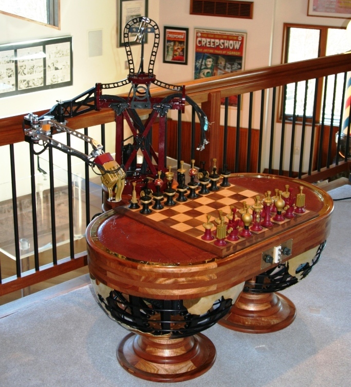
you want to implement something like this? (maybe without the robot? two human players?)
this was done with antennas on each square - later i figured out how to do row and column scanning, similar to the way keypads work - then i removed every other column and every other row and set up system to do intentional cross reads on the spaces where antennas were not physically - this means the hardware becomes pretty simple, but some details have to be paid attention to - how much time do you have on this?
Actually Victor and I are not working together, but is cool to see that I'm not the only one trying to deal with this issue.
This picture does seem to be what I'm trying to do but I will have 2 human players. Since this is my senior project I will have until approx. May 2016 to finish the whole project, but this RFID problem will not be the only feature that I have to implement so I need to address this as quickly as possible. I'm really interested it trying to do this with the intentional cross talk but since I am unfamiliar with RFID implementation I don't want to bite of more than I can realistically handle within my timeline.
Thanks for the advice,
Jerome
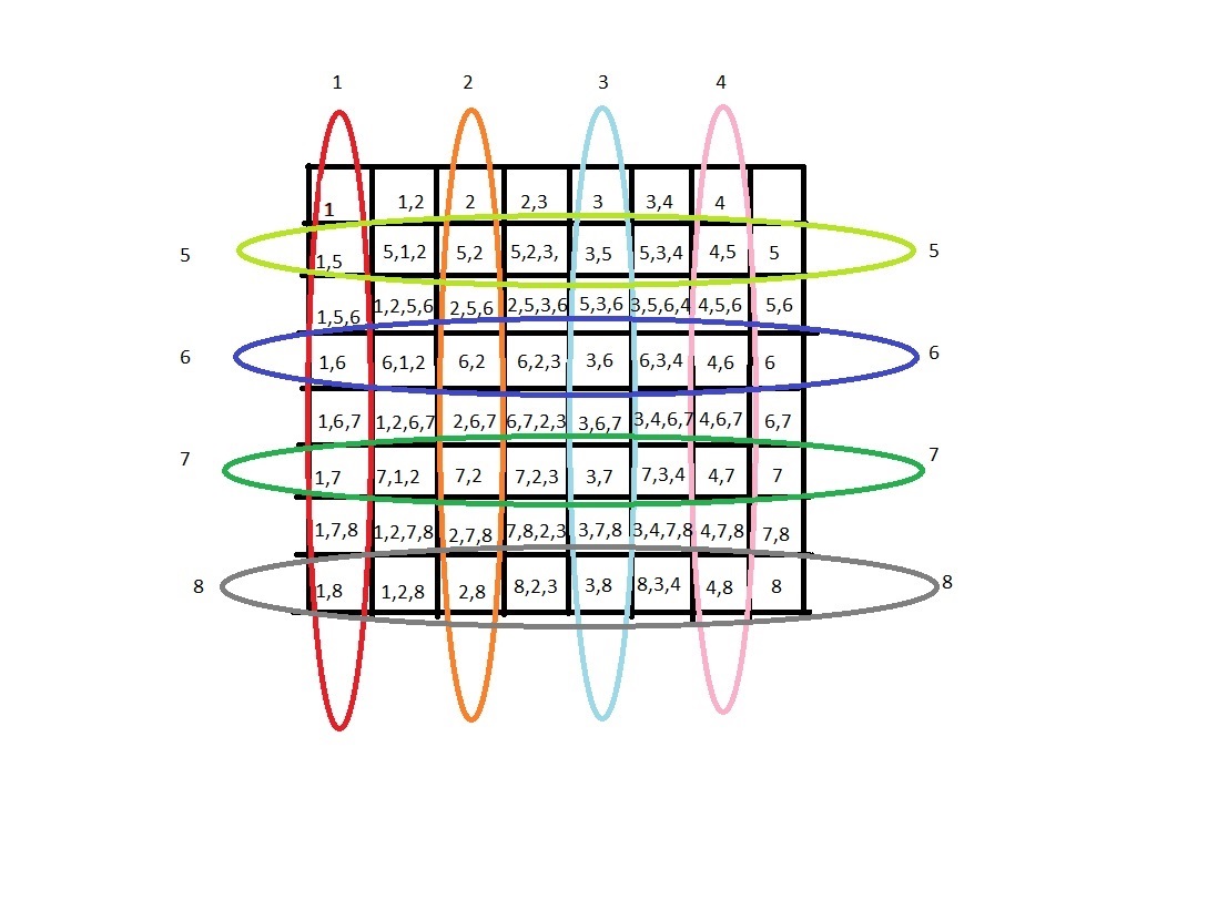
see attached - i just made this for you - don't want to take away your opportunity to design/learn/experiment your own thing, but this should give you a good base to start with. in this case i would choose 1.5" spaces, as this gives you total of 12" x 1.5" to cover, which is doable if you use our 24.2mm tags for the pieces
reader IC can be TRF7964A or TRF7962A and use MSP430FR4133 might be good choice (or similar) and Peregrine Semi SP4T adn SPDT switches work well in this type of application.
since you have plenty of time, the thing to experiment with here is the width of the antennas themselves as it relates to coverage of the adjacent row. What you are trying to do is intentionally cross read and keep track of what you read from which antenna so if you read a tag from four antennas, you know its located on the square in the middle of those four or conversely, if you only read a tag on two antennas, that tag will be where they intersect.
make sense?
Wow this makes all of this so much clearer! Thank you!
One question is that for my application my board has actions to complete between the time the piece is picked up and when it is placed in a new spot. Assuming I wanted to reduce the vertical range of the antenna (if the piece is lifted straight up) to less than the size of each space would I have to simply use a lower power antenna for each column and row opposed to the setup that you showed.
It just seems like the player would need to lift a piece farther than 1.5 inches off the board for the sensor to realized that it has been lifted and if I could reduce that distance that may be a little better.
I hope this was somewhat clear.
Hope you guys are trying to do something like this?
Once you get it working, throw up a demo on you tube and post it here.
Thanks,
JD
I tried doing this using an Arduino and an 8x8 led matrix IC that controls 64 LEDs. Instead of LED I used a relay IC that connects each antennae using only one reader module. The software controls which antenna is connected. The reader then transmit the data read back to the Arduino and relayed to a PC which analyzes the process. I will sow my prototype later post.
Cecil -
yes - if you see this app note - this describes such a system which i implemented completely at least twice and then have a third version of it cut down to just the four.
you can make a "game board" like that - just have to keep it reasonable on the # antennas - if it gets to be too many, then you can revert to a row and column approach on the antennas or an every other row, every other column approach - both of these last two require patience when designing and prototyping as you have to pick a transponder and marry it to the antenna tuning / Q, relative proximity to the other antennas, etc. its a little tricky for a new person, so i would stick with the basic approach to prove your concept out.
so the algorithm is switching through the antennas - the antennas are to be setup to do intentional cross reads on the squares (actually rows or columns) that do not have antennas - that is the advantage to doing it this way (less antennas) - as the alternative is to have antenna on each square or antenna on each row and column - it does require some knowledge, ability and patience to tune the antennas correctly and choose the correct tag size to match the system, but it works.(like this, i think you understand that - just showing here a simplified view of some of the flux lines that would be generated.
to answer you directly - i see what you mean - in that case you would have to rely on UID and RSSI value returned to determine where it was. When i worked on this i considered odd number of antennas to make it work - you could add a dummy column and row to get same effect
image on the right is with antenna on every column and row, image on right is reduced # of antennas as we are discussing, but with 15 x 15 array, as that is what i needed to accommodate with what i did.
Kim -
IMHO - this is not a beginner project from any point of view and all these devices are surface mount, so unless you have experience with SMT assembly (and the correct soldering iron(s) and a microscope with which to mount them correctly, plus access and experience with a network analyzer) I would not attempt, if I were you - you would need to be an expert in these fields to build this in the first place, let alone teach someone else how to do it.
Josh,
I have been fallowing these post and they have been very helpful. I have a question could this type of chess board be set up in an outdoor environment on a bigger scale.
I would like to know if it would be possible if I could measure the distance of multiple objects in an area anywhere from 10 x 10 ft to 20 x 20 ft using RFID tech. For example, Say I have a golf green (mini golf) that is 10 x 10 ft and I would like to know the distance the ball is from the cup (pin) when the ball is on the green or in that area. I would need that information relayed back to me in real time. But also if there were multiple balls on the same hole, I would need to know all their distances as well and if they were to move (if they were hit be another ball).
after reading through these post i figured I could place a HF chip in the ball and possibly create a grid of antennas and readers. Like a chessboard with an antenna under each square and a tag on each chess piece. The reader would fire up each antenna in sequence. When it reads a tag, I know the ID of the tag and the object associated with it. Since the reader identifies the antenna that read the tag, I would know each piece’s location. I believe the same could work with balls on a green? I would like to know is if this is possible to create outside? What types of antennas and readers would I need to use?
Note: The antennas would possibly under fake turf. i also encourage other suggestions on how this could be made possible another way.
Josh, thanks for this interesting thread. Can you explain in more detail on how the above was designed?
Not seasoned on RF circuits so have many questions.
1) is the reader circuit operating @ 13.56 mhz? Read that 125khz may be more practical to intentionally force the SR (short range) pickup of the tags?
2) in the above case, when operating, does each reader antenna pickup only a single tag or does it pickup also nearby tags? if multiple tags are picked up, how did you cancel the surrounding tags from your logic? would be great to have a reader IC at these frequencies with a RSSI register to then isolate and select the tag with the strongest ping value.
3) how close can the antennas be placed without having a negative impact on the operation? thought to place a single antenna inside each 2x2 square. welcome more detail on you were able to skip columns / rows as still not clear on the concept. can you share the PCB antenna layout for the above project? This will assist to reduce the BOM.
Due to the latency of the RFID pickup, will consider to use 1:4 or 1:8 mux as a max in this proof of concept. We would like to start with perhaps a 4x4 grid or 1x8 of antennas and use the mux to cycle the antennas at varying times so that they do not impact each other when the respective square antenna is enabled.
Would a RF balun or similar be more suitable for an intentional short range pickup of the RFID tag? That is, to not pickup other tags that may be sitting along the perimeter of the PCB antenna and want the tag that is center to the antenna layout.
Thanks!!
1) 134.2kHz HDX, 13.56MHz and UHF RFID technologies all have their place in the world.
see attached for a short primer on the three (from an application specific note written about 8 years ago)
RFID Selection Guide for Waste Management Applications.pdf
2) each technology type has their own protocols to handle arbitration of multiple transponders in the field. it would be time consuming to elaborate fully here - but you can read the ISO standards that govern the techs to learn more. To summarize LF - usually a "gate mode" is used, although anti-collision does exist, because of the speed of the air interface, it takes much longer than the other two main techs to perform that. HF tech has multiple protocols which use that band. ISO15693 is the longest range of these and it (as well as ISO14443B) uses a slotted approach for anti-collision. Typically, when looking for tags, the reader would be sending out single slot inventory command (for ISO15693) or REQB/WupB to activate - if and when a collision was detected, the reader firmware would switch to sending out the slotted version of those, then arbitrate. ISO14443A uses anti-collision as part of the activation sequence to begin with. FeliCa uses a slotted approach, but it is a time based one in which the card selects a time slot randomly, based on value sent from the reader during the Polling command. UHF RFID uses a random protocol for same.
3) the idea of doing rows and columns came from previous work i had done on keypads. it was superior to using antenna for each space because it used less antennas (cheaper / easier to route) - then since i knew a few things about magnetics - thought to simplify further by removing every other row and column. it took some effort and experimentation with different tunings, tag sizes, Q values, etc. to get it right.
4) here is an image of a board i made to start with - you could do same
Lastly - a balun is generally not needed in HF RFID...this would be more something that is used for HAM radio applications
Becky -
I would never try this with 125kHz or 134.2kHz - the read range at close distance would require anti-collision which is too slow (because of the data rate possible with low frequency) IMHO for the application.
The high frequency reader i used here was single ended, not differential, so the antennas were all matched to 50Ohms and i switched
you will see i cascaded the switches and also you can see the truth table on page 6