This thread has been locked.

If you have a related question, please click the "Ask a related question" button in the top right corner. The newly created question will be automatically linked to this question.

TRF7962A: The UID number changes.

Part Number: TRF7962A
Other Parts Discussed in Thread: RF37S114, TRF7970A

Hello.
I use the TRF7962A to read the UID of the IC tag [RF37S114].

I occasionally can not read the UID properly.
For example, if reading fails, it will be as follows.
Successful example: 4E 58 A1 66 E 7 C 0 0 7 E 0
Failure example: 4E 58 A1 66 E7 C0 07 52
E0 changes to 52.
If it fails, it always changes to the same number.
When changing to another IC tag, it will change to another number.
Example: E0 -> C1
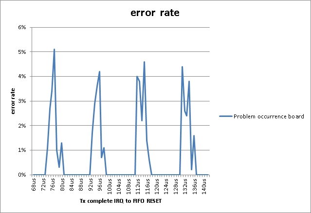
The probability of failing is about 4%.

I know that communication distance affects reading. However, even if communicating at a distance of 0 mm, the result will not change. (In my environment, IC tags can communicate at a distance of 9 mm.)

I use this function to communicate.
Serial Interface Mode With Slave Select (SS)
I saw errata and I got the SPI data on the negative edge. I analyzed the SPI signal by another method, but I got the failed data.

Please tell me what I should be careful in order to get the data correctly.

  • Hello,

    What TI example code are you using as a basis for this?
  • Thank you for your reply.
    I was using the evaluation board of [TRF7970A] for the first time.
    Based on the sample code, I customized it to TRF7962A.
    Specifically, tag IC is read using the following communication.
    The tag IC reading interval is 6 ms at the shortest.

    MOSI
    83
    80
    4F FF
    09 31
    49 FF
    0B 07
    0B 86
    4B FF
    40 00
    00 31
    01 02
    07 15
    08 1F
    6C 00 00
    8F 91 3D 00 30 26 01 00
    41 FF
    6C 00 00
    8F
    41 FF
    6C 00 00
    5C 00
    5C 00
    5C 00
    5C 00
    5C 00
    5C 00
    5C 00
    5C 00
    5C 00
    5C 00 (Read when data is accumulated in the FIFO.)
    7F FF FF FF FF FF FF FF FF FF FF
    8F
    4F FF
    8F
    40 00
    00 91
    0B 07
    4B FF
    6C 00 00

  • Hello,

    That didn't quite answer my question, please provide the TI software number for the example code like SLOC297C or SLOA227A.

    Also it looks like you are polling for IRQ? Why not use an interrupt? And why use half-power mode?

    Are you getting a TX Complete IRQ at any point? That isn't clear to me.
  • Hello
    I am referring to SLOC 250.

    I am reading the data 10 BYTE.
    There is no setting to receive IRQ at 10 BYTE.
    I received an IRQ at 9 BYTE and read the remaining 1 BYTE by polling.

    Below is the reason why it is used with half power.
    · To comply with radio standards.
    - It is possible to obtain necessary communication distance even with half power.

    I am using IRQ.
    6C 00 00
    IRQ is received before the above lead.

    Thank you.
  • Hello,

    That software base is very old and had some bugs as well. We don't support it anymore. I recommend reviewing our much improved and well tested example: http://www.ti.com/lit/zip/sloc297

    As far as the issue itself, without seeing the MISO line, or any timings, it is difficult for me to really comment on specifically what is going on. Ideally, a full logic state analyzer capture would be best, I could probably identify the issue quickly from that. But from what you have shown me, I suspect the issue is related to some sort of timing. You may want to check that you aren't being impacted by any issues reported in this document including the one in Section 1.6: www.ti.com/.../sloa140b.pdf

    You mention half-power to comply with radio standards... I've never heard of this being needed, we have had the device tested and certified even for RED using our recommended hardware design. You may want to talk about that with whoever told you that the output power is too much further. All you are doing is reducing your read range.

  • Hello
    Thank you for your reply.
    I understood what had been affecting this.
    The time from Tx complete IRQ to FIFO reset is affected.
    This time is currently 100 to 150us.
    If this time is lengthened or shortened, it will not occur.

    www.tij.co.jp/.../sloa248a.pdf
    4.6 What Does an IRQ Status of 0xC 0 Mean?
    The typical cause for this issue is not the interrupt for the TX complete event (IRQ status = 0x80) is not serviced quickly enough.

    From QA above.
    I want you to tell [processing time] in order to operate normally.
    The status is not 0xC0 or 0xE0.

    I want to comply with weak radio standards.
    License is unnecessary.

    Additional Information
    E0 changes to the upper byte of CRC.

    Thank you.

  • Hello,

    The 0xE0 you are seeing is the last byte of the tag UID: en.wikipedia.org/.../IEC_15693

    100 to 150 us is fine for FIFO reset, the issue is if you don't service IRQ before tag data is received, so it would be that the IRQ is not serviced across multiple milliseconds.
  • Hello

    I examined various things so far.

    1. Conditions under which an error occurs
    The time from the reception of the transmission completion IRQ to the FIFO RESET was delayed by 1 us in the range of 68 us to 140 us.
    As a result, it was found that an error occurs in a cycle of about 19 us (52.6 kHz).
    Please refer to the attached graph.

    2. Number of error occurrences
    I have 21 TRF 7962A boards.
    The same error has occurred with two of these.
    I did the same thing as 1. on the board which does not generate an error, but an error did not occur.

    3. If you stop FIFO reset
    Stop FIFO reset under the condition that an error occurs.
    Errors will not occur.

    4. IC tag
    There are IC tags that generate errors and IC tags that do not generate errors.
    The error occurred in about 10% of the IC tags.

    5. Output data of IC tag
    When an error occurred, I checked the analog data of the IC tag, but received the data in the normal order.
    However, when the TRF 7962A sends data to the CPU, the data that should have always been 'E0' has changed to the 'upper byte of CRC'.
    That is, 'E0' and 'upper byte of CRC' are interchanged in the TRF 7962A.

    If FIFO RESET is not done, it is written in the FAQ that data corruption occurs.
    However, in my environment, if I reset the FIFO, data corruption occurs.
    Also, the timing at which the data corruption occurs is periodic.

    I have confirmed that there is no problem with the electrical point, but I do not know whether it is the individual difference of the TRF 7962A or what is caused by the slight difference of the external parts.

    I think that 'E0' and 'CRC upper byte' will be interchanged if some internal processing of TRF 7962A and FIFO RESET are combined in a cycle of 19 us.

    As a countermeasure, I decided to mask 'E0'.

    Thank you for your help.

  • Hello,

    That is very odd behavior to me still, however at this point to comment on it further I'd need a full SPI capture with timings between every byte to analyze further. This can be done with tools like the Saleae logic analyzer. If such data is presented then I can analyze it in more detail and possibly identify any timing concerns.