This thread has been locked.

If you have a related question, please click the "Ask a related question" button in the top right corner. The newly created question will be automatically linked to this question.

LAUNCHXL-CC1350: Question about XDS110 in LAUNCHXL-1350

Part Number: LAUNCHXL-CC1350
Other Parts Discussed in Thread: TMDSEMU110-U, TM4C129ENCZAD, AWR1843, AWR1843BOOST

Hello TI engineers.
I would like to ask the following questions first

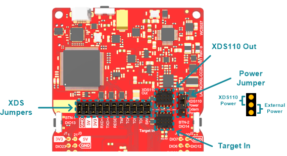
① It is necessary to connect from the LAUNCHXL-1350's XDS110 connector to the 20-pin JTAG connector.

I have a JTAG wiring on a custom board with CTI-20 pins.
(Connector used is FTR-110-03-G-D-06)
Do you have a connector that can convert from 10 pins to 20 pins?

(2) If you come to the conclusion that the question in (1) is not true, is it okay to connect the necessary jumper wires yourself?

(Is it OK to connect only nRESET, TCK, TDI, TDO, and TMS at this time?
The Vtref pin supplies 3.3 V power to the target on the custom board without being tied to a power supply. )

  • Hi Hiroyuki,

    We do not have a connector to convert from our 10 pin jtag connector to 20 pins.

    It is okay to connect jumpers from the XDS110 Out connector. Remember to remove all of the XDS jumpers to disconnect the device on the LAUNCHXL-CC1350 LaunchPad from the JTAG and leave the Power Jumper connected to XDS110 Power, since you want to power you custom board with the 3.3 V supply of the XDS110.

    The minimum connections you need are nRESET, TCK, TMS, 3.3V and GND when using 2-pin mode JTAG and additionally TDI and TDO when using 4-pin mode JTAG.

  • For adapter: Look into the 3 party options, google "20 pin jtag to 10 pin jtag adapter", it looks to be several options.

    TI also has converters, at least according to www.ti.com/.../TMDSEMU110-U 

  • Hi, thanks for your reply.

    From what you said, I can think of the following, is that correct?

    ・There is no adapter that can convert from 10-pin to 20-pin, so you can connect with a jumper wire. (Should they be the same length?)

    -XDS Jumpers must be removed to power the custom board.

    ・As for the connector, it means that VTref also needs to be connected to the custom board.
    (I will post the wiring diagram of my custom board TM4C129 as well.)

  • Hi, thanks for your reply.

    Regarding the adapter, the situation is that it cannot be used because the size does not match in the first place.

  • The custom board flow we designed is as follows:
    What I want to achieve is to turn on the power to each IC and give the TM4C129ENCZAD the XDS110 Emulation function.

    The custom board already has TM4C129ENCZAD and AWR1843 with UART and JTAG connections.
    JTAG pins are connected to TM4C129ENCZAD.

    Each pin of JTAG pin (to connect with the debugger) is pulled from the following part.
    It has 20 pins and is CTI-20.

    ・4, 8, 10, 12, 16, 20: Dropped on the GND layer on the custom board.
    ・7: Dropped to GND via a 10 kΩ pull-down resistor.
    ・5: Connect via a 100 Ω pull-up resistor.
    ・3: Wires without a resistor.
    ・1,11: Connect via a 100 kΩ resistor.
    ・15: A pull-up resistor is used from the NRST pin.

    *The above pull-ups and pull-downs are done on a custom board.
    (TM4C129x and resistors are on the same board.)

    The wiring diagram is as follows.

    5670.Schematic.pdf

  • I'm sorry, it was garbled, so I'll send you a Japanese one.

  • Hi Hiroyuki,

    Thank you for the information.

    Could you please confirm 2 points:

    1. If I understand correctly you have a custom board with an TM4C129ENCZAD that you want to use as an XDS110 debugger, correct?

    2. You also have a AWR1843 device on your custom board that you would like to program with the TM4C129ENCZAD, correct?

  • Hello Diego.
    Thank you for your reply.

    You said
    1. If I understand correctly you have a custom board with an TM4C129ENCZAD that you want to use as an XDS110 debugger, correct?

    I answered
    Yes, That's right.
    We put the TM4C129ENCZAD on our own board, and we are trying to give the TM4C129ENCZAD the function of the XDS110 Debugger.

    You said
    2. You also have a AWR1843 device on your custom board that you would like to program with the TM4C129ENCZAD, correct?

    I answered
    Yes, AWR1843 and TM4C129ENCZAD are on the same board.
    The AWR1843 UART wiring and JTAG connector wiring are connected to the TM4C129ENCZAD.

    -------------------------------------------------- --------------------------------------------------
    I'm sorry, but I have two additional questions.
    The JTAG connector is actually drawn from VTREF, but is this wiring necessary to supply power from JTAG?

    In that case, is it okay to turn on the power to the TM4C129ENCZAD from the power line on the custom board?

    Next, when jumper-connecting between connectors, should the jumper wires be the same length?

  • Let me ask you again, why would you need Vtref?

  • Hi Hiroyuki,

    Since this is related to the AWR1843 radar sensor, I'll be assigning to the radar team so that they can continue providing support.

  • Hi,

    Does your design follow the schematics of the AWR1843BOOST?

    Thank you

    Cesar

  • Mr. Diego
    Hello, Thank you for your Radar team assignment.

    By the way, do you need a VTref?

  • Mr. Ceaser
    Hi, the wiring is basically the same.
    AWR1843 connects UART wiring and JTAG connector.

    When power is supplied to the board, TM4C129 and AWR1843 will be powered on.
    (Would you mind sending me the circuit diagram of the radar you made yourself?)