This thread has been locked.

If you have a related question, please click the "Ask a related question" button in the top right corner. The newly created question will be automatically linked to this question.

CC1352R: Recently upgraded to SDK6.3 from CC13x2-26x2 SDK5.2 and current draw has jumped up by 170uA

Part Number: CC1352R

Apologies for the repost, but it was suggested to me that it would be better to post it on this forum.

Hello all!

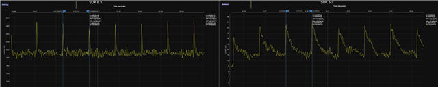
As the title says, we are using a CC1352R and upgrading the firmware from SDK 5.2 to 6.3. After upgrading and verifying the pin and UART to GPIO and UART2 driver transitions are correct and the application still works as expected; we measured the idle current and it has increased from 12uA to 185uA as shown in the included graph.

The application code is for the most the same apart from APIs for those drivers mentioned.

Could these drivers have an impact on the current draw?

I have also checked mcu's manual and it says when in idle mode the RF core draws 170uA. Is it possible the RF core module isn't going into standby mode, how can I debug this? 

Thank you in advance for any help. 

  • It is not possible to answer where the extra current comes from without knowing exactly what is going on in your code.

    I would recommend that you make simple test FW where you are testing one peripheral at the time, and then run the tests with both SDKs, to try to pinpoint where the extra current comes from.

    Once you have some simple code that demonstrate the different current consumption, we can do some debugging here to try to figure out why there is a difference.

    Siri

  • We think we found a bug with the SDK; we noticed our SPI MOSI pins were configured as input enabled in the IOCFG register after the GPIO_init function. We found this In the GPIOCC26XX header file where outputs are mapped with the input enable bit as 1. 

    /* General options remapped directly to IOC defines */
    #define GPIO_CFG_NO_DIR_INTERNAL (IOC_IOCFG0_IOMODE_NORMAL | GPIOCC26XX_CFG_PIN_IS_INPUT_INTERNAL)
    #define GPIO_CFG_INPUT_INTERNAL  (IOC_IOCFG0_IOMODE_NORMAL | IOC_IOCFG0_IE | GPIOCC26XX_CFG_PIN_IS_INPUT_INTERNAL)
    #define GPIO_CFG_OUTPUT_INTERNAL (IOC_IOCFG0_IOMODE_NORMAL | IOC_IOCFG0_IE | GPIOCC26XX_CFG_PIN_IS_OUTPUT_INTERNAL)

    where

    #define IOC_IOCFG0_IE                                               0x20000000
    #define IOC_IOCFG0_IE_BITN                                                  29
    We tried removing the IOC_IOCFG0_IE and this resolved the incorrect IOCFG register and has brought our current draw down substantially, but not fully back to what it was.

    We also checked the SDK 5.20 GPIO driver and there seems to have been a major change to SDK 6.3

  • I have been able to reproduce different currents consumption with the two SDK, and are working with R&D on figuring on why there are differences.

    Siri

  • Please provide me with a simple test code that shows the differences you are measuring.

    You should not have to init the GPIO driver to use the SPI, so it is important that I understand exactly what you are doing in the code.

    Also, are you meaning standby when you say IDLE? 12 uA is a very high standby current consumption, but way to low for an IDLE current, so I am just wondering what exactly you are doing.

    Are you closing the SPI driver when you are done using it?

    I saw a difference in current consumption when changing between the two SDKs, but I was not using the GPIO driver, and the delta was not the same as you saw, so want to understand exactly what you are doing.

    Siri