Other Parts Discussed in Thread: CC1352P, , CC1310
Hi,
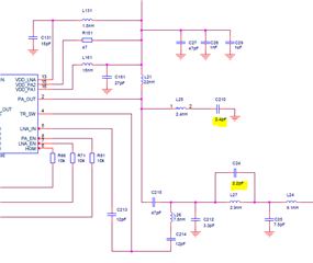
I want to boost the TX power of a CC1352P to 27dbm. I made a pcb according to the application notes and examples of this booster. However, while CC1352P outputs the correct power e.g. 14dbm the booster's output is -30dbm. During the first tests, there wasn't any signal at the output of the booster. After many trials, I found with the oscilloscope, that every time PA is enabled, the voltage at pin VDD_PA2 was dropping to 0, because it is connected to the 3.3v bus through a 47Ohms, as in the schematic. As soon as I replaced the 47Ohm resistor, R151, with a zeroOhm resistor, it started working, but more as attenuator than as booster. In SWRA542, all power pins are connected to 3.3VC, without any resistor in series. The only difference of my pcb , is that I replaced all 0 value components with tracks. Thus PA_IN is connected directly to LNA_OUT. Pcb layout is very similar to the proposed and all components are identical. All RF measurements are done with a Regol RSA310 spectrum analyzer.
Thanks


