Other Parts Discussed in Thread: CC1310, CC1190, SYSCONFIG, CC1352P
Hi,
I am trying to migrate our CC1310 + CC1190 based board with firmware developed around SDK v4.x to CC1312R and SDK v7.x. After reading relevant posts on this forum, I come to the conclusion that this is doable and relatively straightforward. Because CC1312R is basically pin compatible with CC1310, only minor revisions are needed around crystal. On firmware side, we can start with the re-using tx power table for CC13-90 board. I have the following questions related to firmware development:
1) how do we re-use the TX power table? Should we stop generated source and replace the content of txPowerTable_868_pa13 with txPowerTable_subg_US_CC1310_CC1190 ?
In CC13-90/SDK v4.x, the following TX power table is used:
const macTxPwrVal_t txPowerTable_subg_US_CC1310_CC1190[] =
{
    {7, RF_TxPowerTable_DEFAULT_PA_ENTRY(0, 3, 0, 0) },
    {14, RF_TxPowerTable_DEFAULT_PA_ENTRY(1, 3, 0, 0) },
    {18, RF_TxPowerTable_DEFAULT_PA_ENTRY(2, 3, 0, 0) },
    {20, RF_TxPowerTable_DEFAULT_PA_ENTRY(3, 3, 0, 0) },
    {22, RF_TxPowerTable_DEFAULT_PA_ENTRY(4, 3, 0, 0) },
    {23, RF_TxPowerTable_DEFAULT_PA_ENTRY(5, 3, 0, 0) },
    {24, RF_TxPowerTable_DEFAULT_PA_ENTRY(6, 3, 0, 0) },
    {25, RF_TxPowerTable_DEFAULT_PA_ENTRY(9, 3, 0, 0) },
    {26, RF_TxPowerTable_DEFAULT_PA_ENTRY(14, 3, 0, 0) },
    RF_TxPowerTable_TERMINATION_ENTRY
};
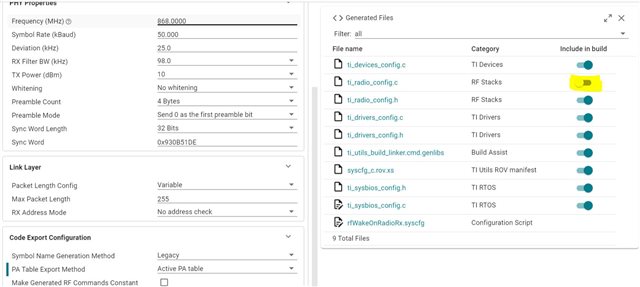
In CC1312R/SDK v7.x based project, the following table is generated:
// generated source
// ti_radio_config.c

RF_TxPowerTable_Entry txPowerTable_868_pa13[TXPOWERTABLE_868_PA13_SIZE] =
{
    {-20, RF_TxPowerTable_DEFAULT_PA_ENTRY(0, 3, 0, 2) }, // 0x04C0
    {-15, RF_TxPowerTable_DEFAULT_PA_ENTRY(1, 3, 0, 3) }, // 0x06C1
    {-10, RF_TxPowerTable_DEFAULT_PA_ENTRY(2, 3, 0, 5) }, // 0x0AC2
    {-7, RF_TxPowerTable_DEFAULT_PA_ENTRY(3, 3, 0, 5) }, // 0x0AC3
    {-5, RF_TxPowerTable_DEFAULT_PA_ENTRY(4, 3, 0, 5) }, // 0x0AC4
    {-3, RF_TxPowerTable_DEFAULT_PA_ENTRY(5, 3, 0, 6) }, // 0x0CC5
    {0, RF_TxPowerTable_DEFAULT_PA_ENTRY(8, 3, 0, 8) }, // 0x10C8
    {1, RF_TxPowerTable_DEFAULT_PA_ENTRY(9, 3, 0, 9) }, // 0x12C9
    {2, RF_TxPowerTable_DEFAULT_PA_ENTRY(10, 3, 0, 9) }, // 0x12CA
    {3, RF_TxPowerTable_DEFAULT_PA_ENTRY(11, 3, 0, 10) }, // 0x14CB
    {4, RF_TxPowerTable_DEFAULT_PA_ENTRY(13, 3, 0, 11) }, // 0x16CD
    {5, RF_TxPowerTable_DEFAULT_PA_ENTRY(14, 3, 0, 14) }, // 0x1CCE
    {6, RF_TxPowerTable_DEFAULT_PA_ENTRY(17, 3, 0, 16) }, // 0x20D1
    {7, RF_TxPowerTable_DEFAULT_PA_ENTRY(20, 3, 0, 19) }, // 0x26D4
    {8, RF_TxPowerTable_DEFAULT_PA_ENTRY(24, 3, 0, 22) }, // 0x2CD8
    {9, RF_TxPowerTable_DEFAULT_PA_ENTRY(28, 3, 0, 31) }, // 0x3EDC
    {10, RF_TxPowerTable_DEFAULT_PA_ENTRY(18, 2, 0, 31) }, // 0x3E92
    {11, RF_TxPowerTable_DEFAULT_PA_ENTRY(26, 2, 0, 51) }, // 0x669A
    {12, RF_TxPowerTable_DEFAULT_PA_ENTRY(16, 0, 0, 82) }, // 0xA410
    // The original PA value (12.5 dBm) has been rounded to an integer value.
    {13, RF_TxPowerTable_DEFAULT_PA_ENTRY(36, 0, 0, 89) }, // 0xB224
    // This setting requires CCFG_FORCE_VDDR_HH = 1.
    {14, RF_TxPowerTable_DEFAULT_PA_ENTRY(63, 0, 1, 0) }, // 0x013F
    RF_TxPowerTable_TERMINATION_ENTRY
};
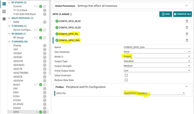
2) How do we initialize CC1190?
In CC13-90/SDK v4.x based project, the following code are used to initialize PA/LNA
void Board_Palna_initialize(uint32_t hgm)
{
    if (hgm)
    {
        if (!palnaPinHandle)
        {
            /* Open PA/LNA PIN driver */
            palnaPinHandle = PIN_open(&palnaPinState, palnaPinTable);

            /* Set IO muxing for RFC GPOs */
            PINCC26XX_setMux(palnaPinHandle, Board_PALNA_LNA, IOC_PORT_RFC_GPO0);
            PINCC26XX_setMux(palnaPinHandle, Board_PALNA_PA, IOC_PORT_RFC_GPO1);
        }

        PIN_setOutputValue(palnaPinHandle, Board_PALNA_HGM, (hgm & 1));

    }
}
// main.c
macUser0Cfg[0].pSetRE = Board_Palna_initialize;

// ssf.c/csf.c
/* Initialize PA/LNA if enabled */
ApiMac_mlmeSetReqUint8(ApiMac_attribute_rangeExtender, (uint8_t)CONFIG_RANGE_EXT_MODE);
In CC1312R/SDK v7.x based project, setRangeExtenderFp_t is no longer a member of macUserCfg_t:
typedef struct
{
    uint32_t               getHwRevision;     /* API to get HW revision */
    uint32_t               *pRfDrvTblPtr;     /* RF Driver API table */
    uint32_t               *pCryptoDrvTblPtr; /* Crypto Driver API table */
    alternateHalAssertFp_t pAssertFP;         /* Assert Function Pointer */
    rfSelectFp_t           pRfSelectFP;       /* RF select Function Pointer */
} macUserCfg_t;
Does that mean we need to just call up GPIO functions to set pins that control CC1190 to desired level in main?
Please advise and thanks.
ZL