Hello,
I'm struggling some strange behavior on CC1310 chip. The problem is that actual transmit time doesn't match calculated.
I guess the issue is in my formula, but please help me to figure out where is my mistake.
I'm working on 9600 baud speed. Packet configuration is:
4 bytes preamble
2 bytes sync word
11 bytes payload (1 byte size + 10 data)
2 bytes CRC (CRC-16-CCITT)
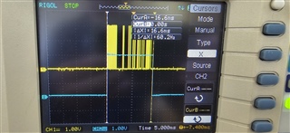
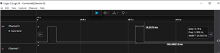
According to my calculations, I am transmitting 19 bytes at 9600 baud, which is (19 * 8 / 9600) * 1000000 = 15833 us
I'm setting delayed TX (which should occur at defined timestamp) and checking difference from the time of the TX finish interrupt. I guess there should be some small difference (about several microseconds)
But as a result I get difference in 879 us, which is too much.
I've also tried to check different speeds, but the drift still exists.
Attaching source code:
/*
 * rfTxTest.c
 *
 *  Created on: Mar 19, 2024
 *      Author: ArchilPirmisashvili
 */


/***** Includes *****/
/* Standard C Libraries */
#include <stdlib.h>
#include <unistd.h>

/* TI Drivers */
#include <ti/drivers/rf/RF.h>
#include <ti/drivers/PIN.h>
#include <ti/drivers/pin/PINCC26XX.h>
/* Driverlib Header files */
#include DeviceFamily_constructPath(driverlib/rf_prop_mailbox.h)

/* Board Header files */
#include "Board.h"
#include "smartrf_settings/smartrf_settings.h"

#define BYTES_TO_US(x) (((x) + 8) * 8000000U / 9600)

/***** Variable declarations *****/
static RF_Object rfObject;
static RF_Handle rfHandle;

/* Pin driver handle */
static PIN_Handle ledPinHandle;
static PIN_State ledPinState;

static uint8_t tx_packet[] = { 10, 0, 1, 2, 3, 4, 5, 6, 7, 8, 9 };
static uint32_t startTXRatTime;
static uint32_t expectedEndTXRatTime;

int32_t diff = 0;

/*
 * Application LED pin configuration table:
 *   - All LEDs board LEDs are off.
 */
PIN_Config pinTable[] =
{
    Board_PIN_LED1 | PIN_GPIO_OUTPUT_EN | PIN_GPIO_LOW | PIN_PUSHPULL | PIN_DRVSTR_MAX,
    PIN_TERMINATE
};


static void TransmitCallback(RF_Handle h, RF_CmdHandle ch, RF_EventMask e)
{
    diff = RF_convertRatTicksToUs((int32_t)(RF_getCurrentTime() - expectedEndTXRatTime));
}

/***** Function definitions *****/

void *mainThread(void *arg0)
{
    RF_Params rfParams;
    RF_Params_init(&rfParams);

    /* Open LED pins */
    ledPinHandle = PIN_open(&ledPinState, pinTable);
    if (ledPinHandle == NULL)
    {
        while(1);
    }

    /* Set RF transmit indication led */
    PINCC26XX_setMux(ledPinHandle, Board_PIN_LED1, PINCC26XX_MUX_RFC_GPO3);

    /* Request access to the radio */
    rfHandle = RF_open(&rfObject, &RF_prop, (RF_RadioSetup*)&RF_cmdPropRadioDivSetup, &rfParams);

    /* Set the frequency */
    RF_postCmd(rfHandle, (RF_Op*)&RF_cmdFs, RF_PriorityNormal, NULL, 0);

    startTXRatTime = RF_getCurrentTime() + RF_convertMsToRatTicks(1000);
    /* Total sent bytes: 4 preamble + 2 sync word + 11 payload + 2 CRC = 19 bytes at 9600 = 15833 us */
    expectedEndTXRatTime = startTXRatTime + RF_convertUsToRatTicks(BYTES_TO_US(sizeof(tx_packet)));

    cmdTx.startTime = 0;
    cmdTx.pktLen = (uint16_t)sizeof(tx_packet);
    cmdTx.pPkt = tx_packet;
    cmdTx.startTime = startTXRatTime;
    cmdTx.startTrigger.triggerType = TRIG_ABSTIME;
    RF_postCmd(rfHandle, (RF_Op*) &cmdTx, RF_PriorityNormal, &TransmitCallback, 0);

    while(1)
    {

    }
}
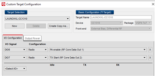
RF configuration:
//*********************************************************************************
// Generated by SmartRF Studio version 2.11.0 (build #122)
// Tested for SimpleLink SDK version: CC13x0 SDK 2.30.xx.xx
// Device: CC1310 Rev. 2.1
//
//*********************************************************************************


//*********************************************************************************
// Parameter summary
// Address: 0
// Address0: 0xAA
// Address1: 0xBB
// Frequency: 868.00000 MHz
// Data Format: Serial mode disable
// Deviation: 25.000 kHz
// pktLen: 30
// 802.15.4g Mode: 0
// Select bit order to transmit PSDU octets:: 1
// Packet Length Config: Variable
// Max Packet Length: 255
// Packet Length: 30
// Packet Data: 255
// RX Filter BW: 98 kHz
// Symbol Rate: 50.00000 kBaud
// Sync Word Length: 32 Bits
// TX Power: 14 dBm (requires define CCFG_FORCE_VDDR_HH = 1 in ccfg.c, see CC13xx/CC26xx Technical Reference Manual)
// Whitening: No whitening


#include <ti/devices/DeviceFamily.h>
#include DeviceFamily_constructPath(driverlib/rf_mailbox.h)
#include DeviceFamily_constructPath(driverlib/rf_common_cmd.h)
#include DeviceFamily_constructPath(driverlib/rf_prop_cmd.h)
#include <ti/drivers/rf/RF.h>
#include <ti/devices/cc13x0/inc/hw_rfc_dbell.h>
#include DeviceFamily_constructPath(rf_patches/rf_patch_cpe_genfsk.h)
#include DeviceFamily_constructPath(rf_patches/rf_patch_rfe_genfsk.h)
#include "smartrf_settings.h"


// TI-RTOS RF Mode Object
RF_Mode RF_prop =
{
    .rfMode = RF_MODE_PROPRIETARY_SUB_1,
    .cpePatchFxn = &rf_patch_cpe_genfsk,
    .mcePatchFxn = 0,
    .rfePatchFxn = &rf_patch_rfe_genfsk,
};

// Overrides for CMD_PROP_RADIO_DIV_SETUP
uint32_t pOverrides[] =
{
 // override_use_patch_prop_genfsk.xml
      // PHY: Use MCE ROM bank 4, RFE RAM patch
      MCE_RFE_OVERRIDE(0,4,0,1,0,0),
      // override_synth_prop_430_510_div10.xml
      // Synth: Set recommended RTRIM to 7
      HW_REG_OVERRIDE(0x4038,0x0037),
      // Synth: Set Fref to 4 MHz
      (uint32_t)0x000684A3,
      // Synth: Configure fine calibration setting
      HW_REG_OVERRIDE(0x4020,0x7F00),
      // Synth: Configure fine calibration setting
      HW_REG_OVERRIDE(0x4064,0x0040),
      // Synth: Configure fine calibration setting
      (uint32_t)0xB1070503,
      // Synth: Configure fine calibration setting
      (uint32_t)0x05330523,
      // Synth: Set loop bandwidth after lock to 20 kHz
      (uint32_t)0x0A480583,
      // Synth: Set loop bandwidth after lock to 20 kHz
      (uint32_t)0x7AB80603,
      // Synth: Configure VCO LDO (in ADI1, set VCOLDOCFG=0x9F to use voltage input reference)
      ADI_REG_OVERRIDE(1,4,0x9F),
      // Synth: Configure synth LDO (in ADI1, set SLDOCTL0.COMP_CAP=1)
      ADI_HALFREG_OVERRIDE(1,7,0x4,0x4),
      // Synth: Use 24 MHz XOSC as synth clock, enable extra PLL filtering
      (uint32_t)0x02010403,
      // Synth: Configure extra PLL filtering
      (uint32_t)0x00108463,
      // Synth: Increase synth programming timeout (0x04B0 RAT ticks = 300 us)
      (uint32_t)0x04B00243,
      // override_synth_disable_bias_div10.xml
      // Synth: Set divider bias to disabled
      HW32_ARRAY_OVERRIDE(0x405C,1),
      // Synth: Set divider bias to disabled (specific for loDivider=10)
      (uint32_t)0x18000280,
      // override_phy_rx_aaf_bw_0xd.xml
      // Rx: Set anti-aliasing filter bandwidth to 0xD (in ADI0, set IFAMPCTL3[7:4]=0xD)
      ADI_HALFREG_OVERRIDE(0,61,0xF,0xD),
      // override_phy_gfsk_rx.xml
      // Rx: Set LNA bias current trim offset to 3
      (uint32_t)0x00038883,
      // Rx: Freeze RSSI on sync found event
      HW_REG_OVERRIDE(0x6084,0x35F1),
      // override_phy_gfsk_pa_ramp_agc_reflevel_0x1a.xml
      // Tx: Configure PA ramping setting (0x41). Rx: Set AGC reference level to 0x1A.
      HW_REG_OVERRIDE(0x6088,0x411A),
      // Tx: Configure PA ramping setting
      HW_REG_OVERRIDE(0x608C,0x8213),
      // override_phy_rx_rssi_offset_neg2db.xml
      // Rx: Set RSSI offset to adjust reported RSSI by -2 dB
      (uint32_t)0x000288A3,
      // TX power override
      // Tx: Set PA trim to max (in ADI0, set PACTL0=0xF8)
      ADI_REG_OVERRIDE(0,12,0xF8),
      // Compensate adjustRatTicks
      (uint32_t)((20000 << 16) | 0x02A3), // 48 bit @ 9600 = 5000 us = 20000 RAT ticks
      // Enabling syncword detection
      (uint32_t)0x008F88B3,
      //Configure new CRC16 polynom
      HW32_ARRAY_OVERRIDE(0x2004, 1),
      // The CRC16 polynome: CRC-16-CCITT normal form, 0x1021 is x^16 + x^15 + x^5 + 1
      0x10210000,
      // Configure new CRC init value
      0xC0040051,
      // The new init value
      0x00000000,
      // Set the SYSGPOCTL register
      HW_REG_OVERRIDE(0x1110, (RFC_DBELL_SYSGPOCTL_GPOCTL2_RATGPO1 | RFC_DBELL_SYSGPOCTL_GPOCTL3_MCEGPO0 | RFC_DBELL_SYSGPOCTL_GPOCTL0_CPEGPO0 | RFC_DBELL_SYSGPOCTL_GPOCTL1_CPEGPO1)),
      (uint32_t)0xFFFFFFFF,
};

// CMD_PROP_RADIO_DIV_SETUP
rfc_CMD_PROP_RADIO_DIV_SETUP_t RF_cmdPropRadioDivSetup =
{
     .commandNo = 0x3807,
     .status = 0x0000,
     .pNextOp = 0, // INSERT APPLICABLE POINTER: (uint8_t*)
     .startTime = 0x00000000,
     .startTrigger.triggerType = 0x0,
     .startTrigger.bEnaCmd = 0x0,
     .startTrigger.triggerNo = 0x0,
     .startTrigger.pastTrig = 0x0,
     .condition.rule = 0x1,
     .condition.nSkip = 0x0,
     .modulation.modType = 0x1,
     .modulation.deviation = 0x50,
     .symbolRate.preScale = 0xF,
     .symbolRate.rateWord = 0x1893, //9600 Baud
     .symbolRate.decimMode = 0x0,
     .rxBw = 0x24,
     .preamConf.nPreamBytes = 4,    // 4 Preamble bytes
     .preamConf.preamMode = 0x1,
     .formatConf.nSwBits = 0x10,    // 2 Sync word bytes
     .formatConf.bBitReversal = 0x0,
     .formatConf.bMsbFirst = 0x1,
     .formatConf.fecMode = 0x0,
     .formatConf.whitenMode = 0x0,
     .config.frontEndMode = 0x0,
     .config.biasMode = 0x1,
     .config.analogCfgMode = 0x0,
     .config.bNoFsPowerUp = 0x0,
     .txPower = 0x46CB,
     .pRegOverride = pOverrides,
     .centerFreq = 0x01B1,
     .intFreq = 0x8000,
     .loDivider = 0x0A,
};

// CMD_FS
rfc_CMD_FS_t RF_cmdFs =
{
     .commandNo = 0x0803,
     .status = 0x0000,
     .pNextOp = 0, // INSERT APPLICABLE POINTER: (uint8_t*)
     .startTime = 0x00000000,
     .startTrigger.triggerType = 0x0,
     .startTrigger.bEnaCmd = 0x0,
     .startTrigger.triggerNo = 0x0,
     .startTrigger.pastTrig = 0x0,
     .condition.rule = 0x0,
     .condition.nSkip = 0x0,
     .frequency = 0x01B1,
     .fractFreq = 0xEB4F,
     .synthConf.bTxMode = 0x0,
     .synthConf.refFreq = 0 ,
     .__dummy0 = 0x00,
     .__dummy1 = 0x00,
     .__dummy2 = 0x00,
     .__dummy3 = 0x0000,
};

rfc_CMD_PROP_TX_ADV_t cmdTx =
{
     .commandNo = 0x3803,
     .status = 0x0000,
     .pNextOp = 0, // INSERT APPLICABLE POINTER: (uint8_t*)
     .startTime = 0x00000000,
     .startTrigger.triggerType = TRIG_NOW,
     .startTrigger.bEnaCmd = 0x0,
     .startTrigger.triggerNo = 0x0,
     .startTrigger.pastTrig = 0x1,
     .condition.rule = TRIG_NEVER,
     .condition.nSkip = 0x0,
     .pktConf.bFsOff = 0x0,
     .pktConf.bUseCrc = 0x1,
     .pktConf.bCrcIncSw = 0x0,
     .pktConf.bCrcIncHdr = 0x0,
     .numHdrBits = 0x08,
     .pktLen = 0,
     .startConf.bExtTxTrig = 0x0,
     .startConf.inputMode = 0x0,
     .startConf.source = 0x0,
     .preTrigger.triggerType = TRIG_NOW,
     .preTrigger.bEnaCmd = 0x0,
     .preTrigger.triggerNo = 0x0,
     .preTrigger.pastTrig = 0x0,
     .preTime = 0,
     .syncWord = 0x00000000,
};
Please suggest.
Thanks in advance,
Archil