This thread has been locked.

If you have a related question, please click the "Ask a related question" button in the top right corner. The newly created question will be automatically linked to this question.

CC1120: Which is better? To use balanced filter (swrr107b design) at CC1120 rf_output or the "handmade" filter of SWRC222 design?

Part Number: CC1120
Other Parts Discussed in Thread: CC1101,

Hi guys, 

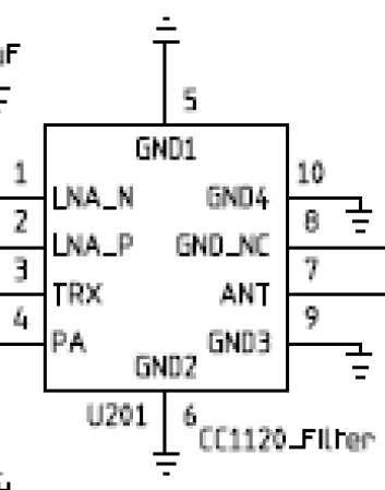
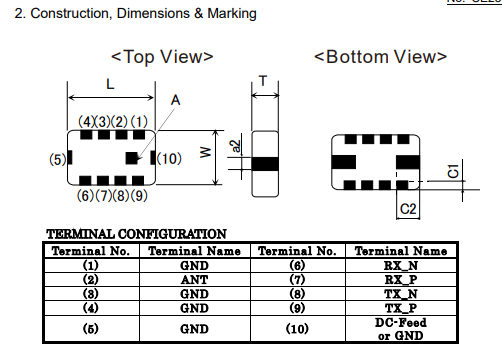
I am converting my old CC1101 designs to CC1120 new designs (4 layers) and I am studying your reference designs for 869MHz and I have found two designs, one with a balanced filter on the RF output of CC1120 [CC112x IPC 868- and 915-MHz 4-layer Reference Design (SWRR107)] and another one with the filter designed with L and C net on the RF output [CC1120EM 868/915 MHz Reference Design (SWRC222)]. 

What do you recommend?

With Balanced Filter:

With LC "handmade" Filter:

Thanks in advance and best regards!

Luis

  • With the IPC you trade some performance with a smaller layout.

    If you want every dB, use a discrete (LC) filter. But if you can afford to lose some on the link budget (compare the app note describing the IPCs and the datasheet for CC1120) and want a small layout and fewer components to source go for the IPC.
  • Thanks a lot for your response, TER.

    Excuse my ignorance, I am searching what is the IPC you are talking about but I don't find it. What is IPC? Or is the nomenclature of the swrr107 design?

    By the way, I am going to consider your recommendation!

    Best regards and thanks again!

    Luis
  • {facepalm} {shame}
    Ok, understood, TER.

    Many thanks!!!! :)
  • Sorry, TER. I see that you are a TI employee and I want to advise you about the Schematic Symbol made for the Murata filter LFD21868MMF1D386 on your Design Note DN039.

    On your document, the schematic symbol (and its pinout) is different with respect the pinout of the filter on Murata Datasheet. However, on the PCB design that appears on DN039 it's ok the footprint.

    I don't know if you use that symbol for any reason or it is an unintentionally mistake, but it is confusing when you use the DN039 for review your own design. For example, in the document you can read: "The Murata IPC requires pin 8 on the IPC to be not connected", but it is really the pin 3 nor 8.

    DN039 Pinout Murata Datasheet Pinout
    Pin 10: GND4 Pin10: DC-Feed or GND
    Pin 9: GND3 Pin 9: TX_P
    Pin 8: GND_NC Pin 8: TX_N
    Pin 7: ANT Pin 7: RX_P
    Pin 6: GND2 Pin 6: RX_N
    Pin 5: GND1 Pin 5: GND
    Pin 4: PA Pin 4: GND
    Pin 3: TRX Pin 3: GND
    Pin 2: LNA_P Pin 2: ANT
    Pin 1: LNA_N Pin 1: GND

    DN039 Symbol:

    Murata Datasheet Pinout:

    I only wanted to advise you.

    Best regards, 

    Luis!

  • Hi,

    The CC1120 IPC schematic symbol was a generic symbol  so the pin numbering is incorrect according to the Murata's or Johanson's datasheet. The connection to the IPC from the CC112x is correct. Illustrated more in the app note. Apologies for the misleading numbering in the schematic. 

    IPC (Integrated Passive Component) is some times known as IPD (Integrated Passive Device) depending on the manufacturing vendor of the passive component/device.

    Regards,

       Richard