This thread has been locked.

If you have a related question, please click the "Ask a related question" button in the top right corner. The newly created question will be automatically linked to this question.

CC1190: Is my CC1190 design saturating

Part Number: CC1190

We are using a Cc1190 to boost the output of a 1GHz transceiver. We power via USB C and a 3.3V LDO. The issue we have is that we get profound sidebands above +18dB power output. we are using a 4 layer board as per the application notes. we are drawing approx 280mA from the power supply so approx 240mA is going to the CC1190.

The measurements are being made using a Tektronix RSA306B and we are using an inline 30dB antennuator, as we have observed similiar effects if we feed directly to the Spectrum analyser due to the input saturating.

The test is made by continuously driving  the CC1190.

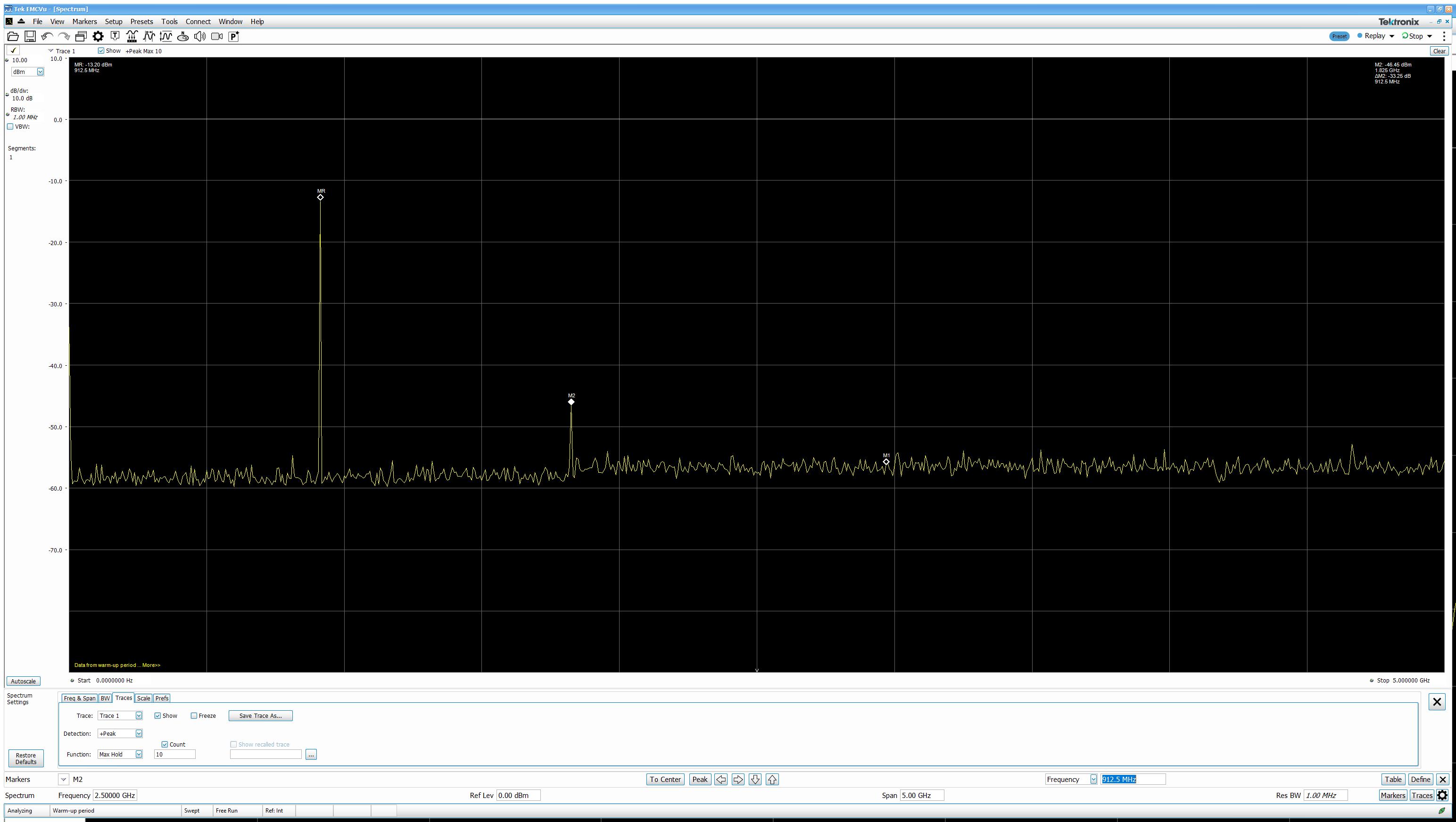
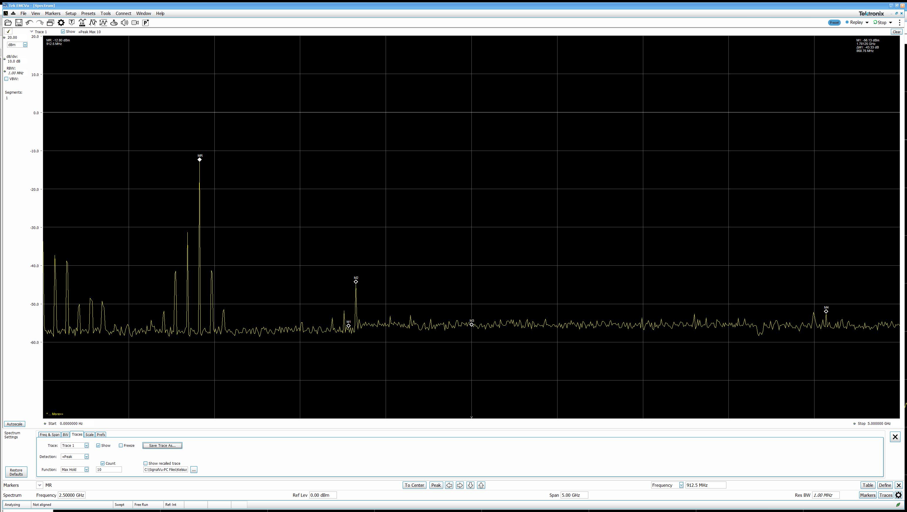
I have attached 2 plots, the effect seems to be evident from power level 5 and above.

  • Hi,

    Our team member from hardware will get back to you as soon as possible.

    Thanks

  • Hi,

    It seems Plot-1 is much cleaner ( No spurs other than Harmonic) than Plot-2.

    What is difference in conditions in between Plot-1 and Plot-2?

    What is meant by Power Level 5? Do you mean +5dBm input Power to CC1190?

    What is the transceiver you are using? Is it a TI device?

    Could you please post your Schematic in PDF and PCB Layout in Gerber format for review?

    If you think your design is confidential then you can send me a Friend request, so that we can use private channel for review.

    Thanks,

    PM

  • Or request a review on: https://www.ti.com/tool/SIMPLELINK-SUB1GHZ-DESIGN-REVIEWS

    Looking at plot 2 it looks you have an unstable design. I would use a line stretcher to see if the spectrum change as a unction on where the load is in the smith chart.  

  • I have sent a friend request before sending the gerbers and schematic.

    The transceiver is a Nordic nrf9E5, it runs a legacy protocol that we have to support.

    I am checking with the SW developer what the differing power levels mean.

    The design was originally a 2 layer board, it is now 4 layer as per the reference design, and the component values have been carried over from the 2 layer version, but they follow the design guidelines in the reference design.

    Many Thanks

    GR

  • Friend request accepted. 

    Do you have access to a line stretcher or are you able to do any for of load-pull to see how the output spectrum changes as a function to the load?