This thread has been locked.

If you have a related question, please click the "Ask a related question" button in the top right corner. The newly created question will be automatically linked to this question.

CC3235S: There is a problem with the I2C waveform.

Part Number: CC3235S

Hi team,

Here's the request from the customer:

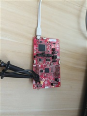
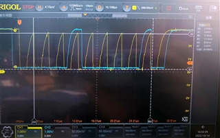
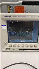
When burning i2copt3001_cpp into CC3235S-LAUNCHPAD, although the communication can be successfully established, the waveform has the following problems when measuring the SCL waveform:

  1. The rising edge rises too slowly
  2. The low level pulled down by CC3235S is not 0, there is a half-high level of 250mV.

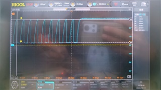
Although this phenomenon does not affect the communication, does this mean that there are some problems with the pin output when the CC3235S controls the I2C? At the same time, customer measured the SDA line and found that the above two problems also exist, but when the slave sends an ACK signal or writes data to the bus, it can pull the low level to 0V, which shows that the slave's control of the bus is no problem.

This phenomenon exists in both customized boards with a 4.7K pull-up resistor and the CC3235S-LAUNCHPAD.

Could you help check this case? Thanks.

Best Regards,                                                            

Nick

  • Hi Nick,

    Has the customer made any modifications to the launchpad? Please confirm which boosterpack you are using.

    Could you ask customer to also probe the I2C_CLK?

  • Hi Sabeeh,

    Here's customer's further reply:

     Launchpad boot with FUNCTION-4WJTAG, pin SOP is 000, no other changes to the hardware.

    The example is I2COPT3001 as well as being compiled under the condition that MCU_Image does not produce IMAGE files. Than the program running through debug and capturing SCL falling edge.

    Is there any problem for the configuration of I2C pins than generating this waveform? How to make the low level to 0V and increase the rising edge speed?

    Best Regards,                                                            

    Nick

  • Hey Nick,

    Could you try flashing the device and then viewing the I2C output? Does it change?

    Are you sure there are no modifications to either the board and the source code? 

  • Hi Sabeeh,

    Here's the reply from customer:

    Hello, when I use CC3235S-LAUNCHPAD to communicate with the OTP3001 device on board, I find that the I2C waveform does not have reliable high and low levels.

    The specific waveform is shown in the figure below, in which the rising edge has a very slow rising time, and the low level generated by CC3235S is not 0V.

    There is no change in hardware and software, and the startup mode is SOP=000.

    I think this I2C waveform is not a qualified I2C waveform although it does not affect communication. I think it should be related to the driving ability of CC3235S to IO. However, I will not modify the specific pin configuration information of CC3235S, and I hope I can solve this problem with you.

    Best Regards,                                                            

    Nick

  • Hey Nick,

    yes this waveform is definitely irregular. Allow me to consult with the hardware team. 

  • Hi,

    May I know is there any update for this question?

    Best Regards,                                                            

    Nick

  • Hey Nick,

    Could you try a different board by chance? If the probes are removed does everything work ok? 

  • Hi,

    Here's the reply from customer:

    The board we designed ourselves will also have the same problem, and the phenomenon that the low level is not 0V only occurs when the CC3235S occupies the control of the I2C bus.

    This waveform may not cause I2C communication to fail, but it is undeniably an abnormal waveform.

    I'm not sure what you mean when you say everything works ok. For the P01 and P02 pins used by I2C, their low level is not 0V as a common IO. I think this is related to the external pull-up resistor. , but I can't explain this phenomenon; the high and low levels are normal for the rest of the pins without external pull-up resistors.

    I would like to know do you have waveforms for testing launchpad there, do you have the same problem as me?

    Best Regards,                                                            

    Nick

  • Hi Nick,

    What I meant by "everything working ok" is if there were any issues in the example software. 

    I'll try to produce the issue on a launchpad and capture a scope of the I2C communication. 

  • Hi Sabeeh,

    The examples are all unmodified, and no problems were found. But there is a phenomenon that even if the P01 and P02 are used as GPIO mode in push-pull output mode, the low level will not be 0V. However other IOs without external pull-up resistors do not have this problem. Customer think that it is caused by the pull-up resistor. But how can they ensure the IO low level to 0V when there is a pull-up resistor?

    They have no idea about it and look forward to your guidance and waveform test results

    Best Regards,                                                            

    Nick

  • Hi Nick,

    Apologies for the extended delay, I went into the lab today to probe the I2C bus, and I see a very similar result. I do not believe this is an issue. Also, the FW is behaving correctly so even though the I2C lines do not look "correct", the device is functioning correctly. 

    These slopes are coming from the capacitance of the board and trace layout onto the traces and that is how they are getting "smoothed" out, ie. there is a parasitic RC constant.