Part Number: CC2520
Other Parts Discussed in Thread: CC2530, SMARTRFTRXEBK
Hi,
I've been attempting to get the CC2520 on our custom board into a continuous tone transmit mode for FCC test, but so far I've been unsuccessful. It seems like this question and answer should be exactly what I needed to find:
... but I've tried the register settings from that solution without success. I've also tried writing ALL of the register settings supplied by SmartRF Studio to our board to make sure there wasn't some other register setting that mattered.
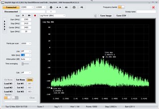
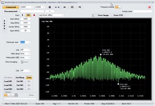
If I have it send a packet of all 0xA5 data normally, I get a nice bell curve with a bunch of stuff under it as follows, which make sense:
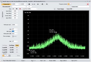
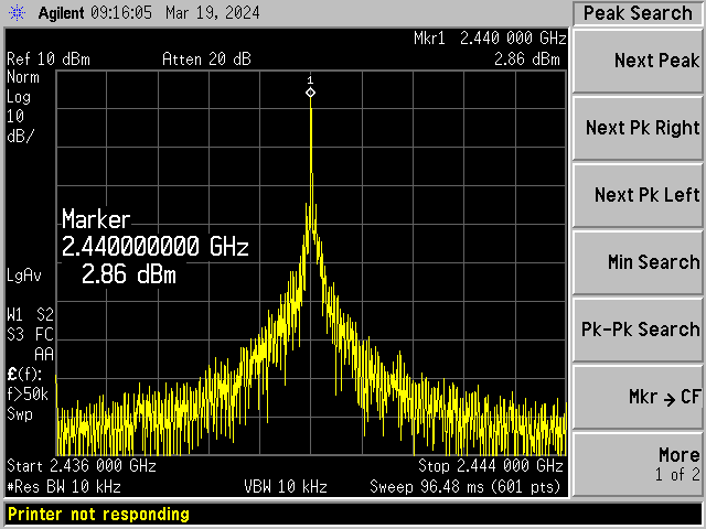
When I change FRMCTRL0 from 0x40 to either 0x42 or 0x43 and set the CC2520_INS_STXON bit to start transmission, I get the same bell curve, though with nothing under it as shown:
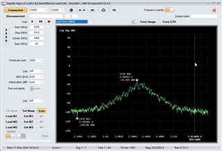
I assume what this is telling me (because the bell curve is just as wide as it was when sending real data) is that it's still sending modulated data, it's just all zeroes now. I thought I'd see a narrower peak for unmodulated data. Is that a correct assumption? I also thought that with FRMCTRL0 set to 0x43 it would look kind of like the first image, with random data being sent.
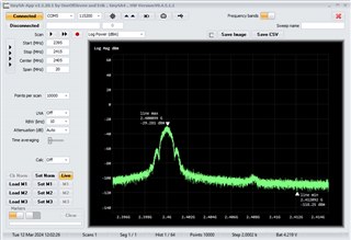
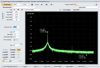
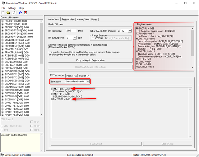
Experimentation showed that all combinations of 0x65 vs 0x05 for mdmtest0 and 0x42 vs 0x43 for FRMCTRL0 result in this same bell curve with nothing under it.
Maybe there is something wrong with how I'm kicking off the transmit or some other configuration issue. Is there some sample code somewhere (maybe the source code for SmartRF Studio) or some other information out there showing *all* of the steps I need to take to get the radio into continuous unmodulated transmit mode?
Thanks,
Glen