CC2652RSIP: How to work with interrupts and OSAL (gp sink)?

Part Number: CC2652RSIP
Other Parts Discussed in Thread: Z-STACK

Tool/software:

Good morning,

in the last few months I worked with zc_thermostat_sink (sdk 4.40) customized version to receive temperature data from a green power sensor.

But the device is designed to perform other tasks in addition to receiving RF data.

The most time consuming is the acquisition from 3 ADC channels @4kHz.
The design is the following:

  1. An ISR, triggered by a timer related HWI, kicks the ADC conversion for channel 0;
  2. The EOC ISR copies the value and triggers conversion for channel 1;
  3. The EOC ISR copies the value and triggers conversion for channel 2;

With the previous version (RF protocol IEEE 802.15.4 and sdk 3.40) all actions were completed with a low jitter.

Now, instead, sometimes happens that timer triggers a new HWI before the acquisition of the 3rd channel is completed.
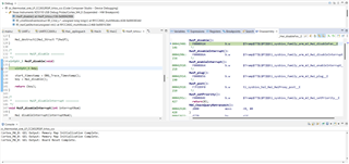
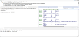
Analyzing the problem by having inserted some trace instructions that write in a circular buffer in ram, I've seen that the OSAL disables all the interrupts, delaying the execution of Timer ISR/EOC ISR for several CPU cycles (even 3700 that @48MHz are about 77µs.).

How can I resolve this situation?

Thanks very much,

  • Hi,

    Thanks for the details and analysis.

    How often is the issue happening?

    So if I understand correctly:

    A) Between each step 1, 2, and 3, the device is NOT in an interrupt.
    B) Then threads are allowed to run (such as Z-Stack thread).
    C) But in some cases interrupts are disabled prior to 3 triggering, resulting in a delayed conversion
    D) The delay in C) then bleeds into the timer ISR which triggered step 1?

    If that is the case, then I think you can keep track of a state variable on which step is active (1, 2, or 3), then if the timer triggers, that ISR can check the state. If the state is 2 (meaning step 2 is done and step 3 is yet to occur), then the Timer ISR can schedule it's next timeout at ~77usec. Then after step 3 is complete, that EOC ISR can stop the Timer and start it again with the original timeout.

    OSAL is likely updating some variables atomically within a Critical Section (CS), which would involve disabling interrupts. This complexity is driven by the extra Zigbee components, such as network layer, which would not apply to a direct 802.15.4 example (e.g. ti154stack sensor or collector).

    Thanks,
    Toby

  • Good morning Toby, 

    thanks for your reply.

    The frequency changes on the basis of the number of sensors, we would like to support 12 sensors, and in this case happens all the time.

    In the OSAL CS, we re-enable both interrupts, and now occurs some times.

    I will discuss about your suggestion with the architect who designed the ADC solution and I will be back to you.

    Thanks again.

    Cristiane Bellenzier Piaia

  • Hi,

    change the design to start the timer after second point may mean, perhaps, a lost conversion. 77usec is a long time.

    We are trying to understand who else is disabling the interrupt besides OSAL, to do this we would like to calculate the latency of the interruption but I can not enter in the Hwi_disable code and when I try to include a breakpoint I get this message:

    I can not go besides the line 136.

    I think is because is executed on ROM. 

    All optimizations are disabled.


    How can I debug this code?

    Thanks in advance,

    Cristiane Bellenzier Piaia

  • The Hwi_disable just disables interrupts. I don't think that particular function needs to be debugged.

    In your callstack, you can see what function had eventually caused HwiP_disable to be called.

    For example, in your first screenshot, it is UARTCC26XX_read.

  • Hi Toby, thanks for your reply.

    Just to update you, I can debug when I disabled the ROM in the cfg file.

    In the end, HwiP_disable call Hwi_disable.

    Today I will calculate who is disabling the interrupts for a long time and I will come back to you.

    Thanks again for your help.

    Cristiane Bellenzier Piaia

  • Hi Toby,

    How can I rebuild rf_multiMode_cc26x2.aem4f? I tried to rebuild the drivers folder (using gmake.exe), but these binaries are not rebuilt.

    Thanks again.

    Cristiane Bellenzier Piaia

  • Toby is on a well-deserved vacation until 9/9, so I can try to assist until he returns.  The necessary resources are not provided with the release SDK to rebuild the RF drivers as with other peripheral TI drivers.

    Regards,
    Ryan

  • Hi,

    thanks for your answer. Just for your knowledge I was able to regenerate rf_multiMode library by creating a new project to generate a static library and after including in my project.

    I made a little change in the Hwi.c file to understand how long the ISR are disabled, this information is important for me because as I said previously in this thread, I need to execute 3 ADC conversions in 250 microseconds (@4kHz) executed by ISR.

    I can see that the ISR are disable for a lot of time by the mac functions. For example:  

    Function Delta time (current time - start time) 
    macTxStartQueuedFrame 3857 / 48MHz = 80microseconds
    macSymbolTimerCount 10085
    macPwrVote 2424
    macSendReceiveCmdIeee 7197 
    macRadioTxGo 6819
    macSymbolTimerEventHandler 3864
    macRxFrameIsr 3802
    macRxOn usually 1500 but sometimes more
    macRadioUpdateTxPower 3780

    The delta time is calculated as follows: the current time is obtained from the HWI reset and the start time is obtained from the deactivate of HWI.

    Unfortunately can not afford to stay all this time with the ISR disabled.

    Both ISR (GTimer and HWI) are priority level 1.

    Thank you in advance,

    Cristiane Bellenzier Piaia

  • The radio will take priority to ensure Zigbee connection stability and network protocol is maintained.  Have you considered using the Sensor Controller to record your ADC values and store them in a buffer?  This way the ADC measurements on the SCS CPU is uninterrupted by the main CPU's handling of the radio core, and the main CPU can read the full buffer after it frees from the radio?  The buffers could be read immediately during the time periods where the radio is not used.  Please see the Sensor Controller Studio Documentation and other relevant documentation.

    Regards,
    Ryan

  • Good morning Ryan,

    thank you for the reply and for your suggestion.

    Unfortunately I can not use the sensor controller to do this because it has another task, it is working to control when the power is failure.

    Thanks,

    Cristiane Bellenzier Piaia

  • Are you not able to accomplish both tasks with Sensor Controller?  The ADC Logging can hopefully take less than 50% of the available RAM.  Here are some App Reports if you are not already familiar with them:

    https://www.ti.com/lit/swra586 
    https://www.ti.com/lit/swra585 

    Alternatively, can the power failure code be moved to the main IC since this event does not occur as often as the ADC measurements?

    Regards,
    Ryan

  • Hi,

    As the radio disables all interrupts that causes malfunction of the ADC task, and if I understood correctly, it is impossible to perform any change in this code, the only option is to use the sensor controller to perform this task.

    Before we start to spend some effort for this big change, we would like to understand if the sensor controller can perform the conversion of the 3 channels respecting the correct time (we need to convert 3 channels in 4kHZ sequentially). We have little experience with the sensor controller, so we would like to understand if the sensor controller can execute just the conversions or some other processing with the samples.

    Thanks,

    Cristiane Bellenzier Piaia

  • The best information on Sensor Controller Studio can be found by exploring the Documentation and default ADC examples which are provided.  There should be no issue with sampling/conversion of 3 ADC channels every 250 microseconds, with time remaining for rudimentary processing before storing to be passed to the main CPU.  Please let us know if you experience any difficulties while implementing this design.

    Regards,
    Ryan

  • Hi Cristiane,

    The frequency changes on the basis of the number of sensors, we would like to support 12 sensors, and in this case happens all the time.

    Please provide the necessary conditions to replicate this issue.  Is it possible to achieve with one zc_thermostat_sink and gpd_temperaturesensor where the default report rate has been accelerated?  Is a GPD necessary or could it also occur with a zed/zr_temperaturesensor project instead with the poll rate increased?  The goal is to replicate this behavior with the default TI examples and as few code changes and devices as possible.  What is your ADC sampling duration and are you able to detect ADC failure and thus re-sample to recover?

    Regards,
    Ryan