This thread has been locked.
If you have a related question, please click the "Ask a related question" button in the top right corner. The newly created question will be automatically linked to this question.
Hi!
We are designing the CC2652P based hardware and I have a few questions about the pinout. We are expecting to use it as a ZNP, sending commands from other uC Host using UART interface.
In our previous hardware, we were using CC2530 where we should set CFG1 to GND to enable UART interface.
For CC2652P firmware, I am using the one for CC1352P
There, I see that UART0 is configured
Could you please confirm that this pinout is ok? they should be PIN 18 and 19 as in CC2652P datasheet:
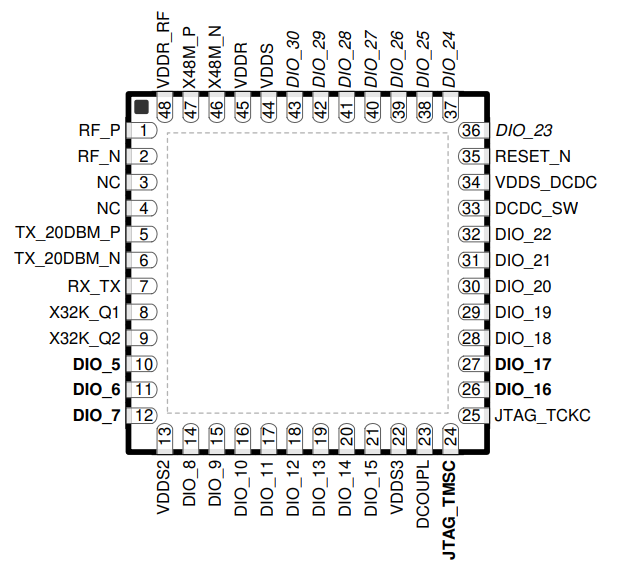
I got confused because in reference design (based on CC2652R -not P-) it uses PIN 19 and 20:
And finally, where in CCS do I select whether if I am using SPI or UART? Is there any other configuration such as CFG0->GND in CC2530?
I want to be sure that I will be able to communicate with the CC2652P Coordinator ZNP from my uC Host using UART.
Thanks!!
Hi Tomas,
The CC2652P is pin-to-pin compatible with the CC1352P and you can use the same UART configuration accordingly. http://dev.ti.com/tirex/content/simplelink_cc13x2_26x2_sdk_4_10_00_78/docs/zigbee/html/cc2652p/software-on-cc2652p.html
The only pin difference between these devices and the CC2652R is the existence of pins DIO_[0-4] and placement of X32K_Q1 (all concerning pin numbers 3 through 9).
The SIMPLELINK-CC13X2-26X2-SDK ZNP only uses UART for communication, the SPI interface controls the external flash memory. You do not need to worry about individual register control on these devices like with the CC2530.
Regards,
Ryan
Hi Ryan, thanks for your answer!
I will then use DIO12 as RX and DIO13 as TX.
One last question, what about hardware flow control (RTS and CTS)? It does not allow me to set it in syscfg.
Anyway, I do not need flow control so if it works without it, it's great for me. I just want to make sure that I have all the proper hardware connections in my schematic.
Thanks!
Hello Tomas,
The "Flow Control" radio button is disabled most likely because the "Use Hardware" option is set to "XDS110 UART" which does not connect the RTS/CTS pins, if you were to change this to "None" then you'd be able to assign pins accordingly.
Regards,
Ryan
Hi Ryan,
I do not fully understand what XDS110 UART is, where can I find more information about it?
Would you recommend me to use it? or to use other pins configuration for my UART? (I do not need flow control).
Thanks!
Hey Tomas,
It is the on-board programmer/debugger and back-channel UART interface for TI's LaunchPad EVMs, please refer to the LAUNCHXL-CC1352P for more information. http://dev.ti.com/tirex/explore/node?node=AOL0GRjJpgV9vbt7pq0lVQ__FUz-xrs__LATEST
Regards,
Ryan
Great Ryan, thanks.
Just to be on the sure. This back-channel UART will work for me to use the CC2652 as ZNP, right?
Thanks!
Yes, this is how the LaunchPads communicate with Z-Tool or ZIGBEE-LINUX-SENSOR-TO-CLOUD for the ZNP and with the terminal UI for application examples. These are all for computer host interfaces and will not be required if directly connecting a MCU host.
Regards,
Ryan
Hi Ryan,
Right Now, we are finishing the schematic of our custom transceiver design. We are using the CC2652P IC, on it's datasheet it recommends to use as reference designs the CC1352P designs. I have problems in defining the BALUN/IMPEDANCE MATCHING Network (I attach a picture of my actual Balun network).
I looked at two reference designs of the CC1352P and their BALUN/IMPEDANCE MATCHING network it's different. I would like to know what network should I use. I refer to the CC13xx/CC26xx Hardware Configuration and PCB Design Considerations and in the Table 1. CC13xx/CC26xx Reference Design Overview (I attach a picture) and the recommended designs are LAUNCHXL-CC1352P-2 and CC1352PEM-XD7793-XD24-PA24. These two designs have different BALUN/IMPEDANCE MATCHING network, which one should I use?
Thanks!
Great question Tomas, I would expect either to be acceptable but I will loop in the HW Team to further comment. At any rate you will need to further evaluate the custom board performance as explained in Section 10 of SWRA640 with RF tests, impedance match analysis, and component tuning.
Regards,
Ryan
Tomas,
Comparing the LAUNCHXL-CC1352P-2 and CC1352PEM-XD7793-XD24-PA24 schematics, the baluns are the same. The impedance matching is different because these are two different boards with difference stackup/RF circuit design.
Since your custom board's stackup and RF circuit design will also be different from these two designs, you will need to perform impedance matching yourself once your boards are fabricated.
BR,
Seong
Tomas,
Apologies, after taking a closer look, it is the filters that are different between the two schematics. I advise that you follow the LAUNCHXL-CC1352P-2 reference design.
BR,
Seong
Hi Seong,
Thanks for your answer. I need to make some modifications to the reference design of LAUNCHXL-CC1352P-2 because we only use the 2.4 GHz 20 dBm Output, so instead of connecting the RF output to the SKY13317-373 (antenna switch), I have to connect it to an 50 ohm antenna. I attach a picture with some questions.
Thanks!
Sorry, I was missing the antenna switch. However, I have a few questions, so I create this new post in order to ask all of those related to my design:
https://e2e.ti.com/support/wireless-connectivity/other-wireless/f/667/t/903297
Thanks!