This thread has been locked.

If you have a related question, please click the "Ask a related question" button in the top right corner. The newly created question will be automatically linked to this question.

Beginner Guide for CC Debugger and 2430Db

Other Parts Discussed in Thread: Z-STACK, CC2530, CC2430, CC2530EMK, CC-DEBUGGER, TIMAC

Hi there.

I have just handed over CC Debugger and a Development Board (i think its 2430DB) by my university. I have gone through the CC Debugger PDF and got to know what it is and how it can be used. Main problem is the manuals are all in Japanese language and i cant read them.

Now i have a few queries regarding these things

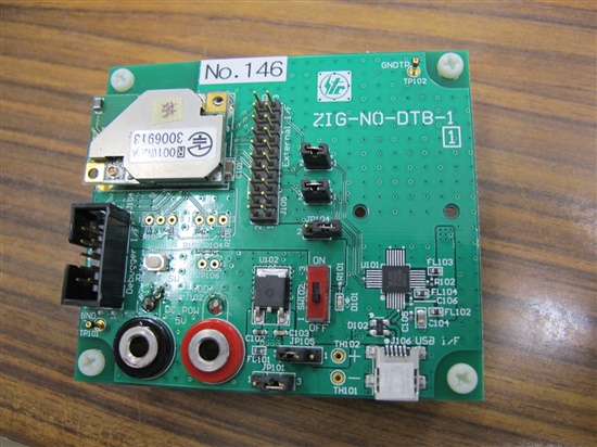
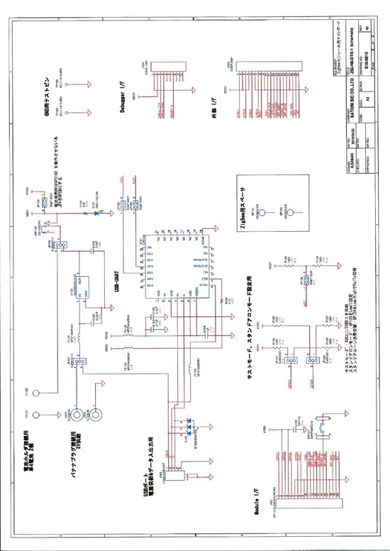
1- How to know which Development board i have?

2- My Board is also having a Zigbee Module installed on it, how can i get started with that?

3- I have downloaded IAR Workbench, how to use that for my development board and CC Debugger?


Waiting for kind suggestions

  • Hi,

    You will find manuals for all of the kits and for the CC Debugger in english on the TI web. If you have a CC2430DK the web address is: http://focus.ti.com/docs/toolsw/folders/print/cc2430dk.html.

    Information about CC Debugger can be found here:

    http://focus.ti.com/docs/toolsw/folders/print/cc-debugger.html

    1) Can you check the printed name of each of the boards you have? Then we can point you to the right documentation for the kit that you have.

    2) You can download the ZigBee stack from here: www.ti.com/z-stack. Make sure that you download Z-stack for the right hardware that you are using. After installing Z-stack you will find documentation in the installed folder. I would recommend to start with the document  Z-Stack User's Guide - CCxxxx.

    3) You will find information on this also on the kit website and in the Z-stack documentation.

    Regards,

    Bjørn

  • thank you for your kind reply and sorry for the late reply, i was actually out of country.

    So back to the problem, i have attached the picture of the board i am using the no. on it says ZIG-NO-DTB-1 , dont know what board it is, i hope you can recognize it for me, here is the image of it.

    I hope you help me out which tutorial should i go for using this board.

    waiting for your kind reply.

  • Hi,

    I have never seen this board before. It is not one of the TI's own ZigBee platforms, but it might be a module provider using a TI chip. Do you not have any other information where this board came from?

    Regards,

    Bjørn

  • This board is made by a Japanese Company named "Satori". Dont have any other information regarding this board.

    By the way even if its a module provider board using TI Chip, how can i use this board to program and then use it to transfer information (data) between 2 Zigbee modules.

    What i want to do is, transfer some bytes between these two boards , both having Zigbee module installed on them and using Zigbee communication i want to send some bytes from 1st Module to the 2nd wirelessly. Can i do this using this board?

  • Hi,

    I would recommend to check with Satori if they have some code examples and documentation for this board.

    Without knowing more about the board it is difficult to answer your question. It they do not have any code examples it might be possible to port TI's Z-stack to this board, but it requires some effort and schematics of the board.

    Regards,

    Bjørn

  • Yes they have the documentation to this board but again the problem is , the documentation is all in Japanese which i cannot read. They Guy from Satori said they are using the same Sample Code in IAR Workbench as 2430DB, so i was wondering if i can treat this board as 2430DB?

  • Hi,

    Without any documentation this will be only guessing from my side. But I guess you could give it a try, and see if things work.

    Regards,

    Bjørn

  • Hi there.


    My efforts are still to no avail. I however got a schematic for my device somehow , may be someone can look at it and let me know if its 2430DB or not?


    Waiting for some suggestions


  • It's very difficult to read the posted schematic - it might be better to attach it as a file instead of inserting it as an image.

    Anyway, from the looks of it, this schematic shows a carrier board for a ZigBee module. It has a USB-to-UART bridge, a voltage level converter and some headers to have access to the I/O of the module. There is a separate debug connector, and the signals (and placement of signals on the connector) suggests that the module is based on a CC2430 or CC2530 device.

    There's no LEDs or Buttons on the board, and no onboard debugger capabilities, so it would be difficult to compare it with a CC2430DB (which has a lot of peripherals). This is more simialr to e.g. a CC2430EM + Battery Board (CC2530EMK + SOC-BB).

    So here's a couple of suggestions: First of all, you will need a CC-DEBUGGER to connect to the RF device/module (for programming and debugging). The normal 2x5 pin cable connector should fit the header on the board, and the pin-out seems to match. Note that you need to power the board from a separate power supply. Impossible to see from the schematic what the input voltage range should be, but it seems that you can set a jumper to bypass the regulator, so supplying e.g. 3.3V should work just fine. Now, with the debugger connected  and the board powered, you should be able to establish contact with the device (i.e. LED on CC Debugger should be GREEN). Open  SmartRF Studio to check what device you have.

    Next, you can download the appropriate ZigBee Sample app to the device. However, since there's no buttons on the board, and since some of the sample apps require some sort of user interface, you might need to tweak the demos a bit.

    Hope this helps.

  • thank you for your informative post. I am studying about these boards but i need some directions on what to study (which board actually i am dealing with). Yes i already have a CC Debugger and i have already gone through its manuals. i have already downloaded IAR Software and studying about that as well.

    As i already explained, i need Zigbee modules to communicate with each other using these boards, and for that i need to develop a software, i am planning to develop the software in VB.net for now, i hope its not gonna make much of a difference if its VB or C, right?? I am carrying some other Zigbee modules (Xbee Pro) and i used Serial communication to make those modules talk, that worked well for me.

    As for the file attachment, i have a pdf of this schematic, which i am hooking up with this post.


    8308.Image110527151205.pdf


    BTW i just connected CC Debugger and the Chip, Green light is ON on CC Debugger, SmartRF Studio 7 says the following in list of connected devices

    "CC Debugger (USB Device ID=5307, Firmware revision=0007), -- CC2430"

    This means i have got a CC2430 chip right? Is it that CC2430 has some extensions also, like CC2430DB, CC2430DK, or its on CC2430 in my case?


    Hoping for kind help.


    Thanks.

  • Anyone on which z-Stack should i go for CC2430??

  • We no longer recommend to design new ZigBee systems based on CC2430, so the Z-Stack for CC2430 is no longer available. We recommend using CC2530 instead.

    In your case, it might make more sense to start looking into the CC2530 ZigBee Network Processor concept. It should be easeri to start working with and for understanding some of the basic concepts of ZigBee. The kit you would need is called CC2530ZDK-ZNP-MINI and it is available for $99.

    For CC2430, you could of course use just the TIMAC (http://focus.ti.com/docs/toolsw/folders/print/timac.html), which is the fundamental building block for the ZigBee network stack.

  • Thank you so much, your post was of great help, i did a "Rebuild ALL" and Debugged it, so devices are now ready with all the lights on them.

    Here is my understanding.

    1 - Installed the Drivers.

    2 - Used CC Debugger to insert the Firmware (may be i am exaggerating that program with Firmware) for Zigbee chips.

    3 - Now my devices are ready to communicate with each other.

    Since i dont have switches on my devices, i am planning to send/receive data using the Serial Port (Mini USB port) on these devices, is it possible? Can i use simple Serial communication program to make these devices talk to each other?

    Waiting for the kind reply.

    Thank you.

  • I have tried making these devices communicate with each other using Serial Communication in VB.net but its not working for me, is it that i am using the wrong Z-Stack? Or is it that simple Serial communication is not going to work this way for these devices?

    BTW i m using this Z-Stack = ZStack-CC2430-1.4.3-1.2.1.exe

    Waiting for kind reply.