This thread has been locked.
If you have a related question, please click the "Ask a related question" button in the top right corner. The newly created question will be automatically linked to this question.
Hello!
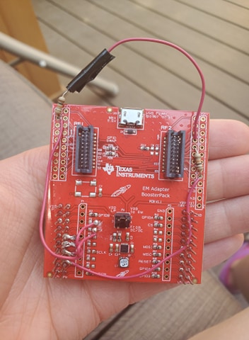
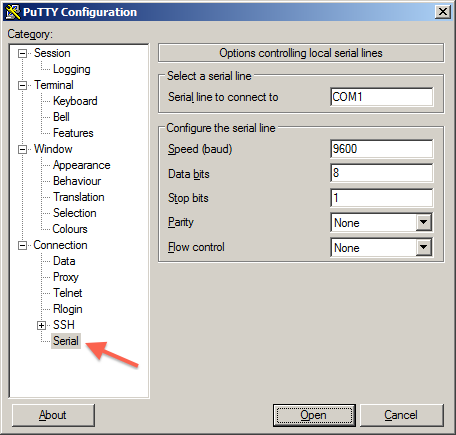
I'm trying to get two CC2538 board communicating with each other using the TM2C123GXL boards, and I have some questions about it:
Do you mean to use TM2C123GXL as host MCU to control CC2538 ZNP and make such two boards to communicate wireless to each other. If so, you can refer to ZNP Host Framework Design Guide and TIDC-ZNP-HOST-SW3.
Hi Tessa,
I recommend that you refer to the Zigbee Network Processor (ZNP) project along with the Monitor and Test API that it uses to communicate with a host. Z-Tool (included in the Z-Stack 3.0.2 downlaod) and ZIGBEE-LINUX-SENSOR-TO-CLOUD are also good host example references.
Regards,
Ryan
Hey, Ryan!
It looks like the Z-Tool is used for the SmartRF06 board. I do not have this board unfortunately. My current set up is using the TM4C123GXL board, the EM Booster Pack and the CC2538 board. My end goal is to have five of these nodes set up in a star topology (one board in the middle as a central node, the other four as end devices). I only want to obtain the node's ID and the RSSI values between each end node and the central node. For right now (just to get started), my goal is to just get communication between two of these nodes established. Can I use the Z-Tool with this? Or does it have to be with the SmartRF06 board? If yes, then how can I do this? If no, then is there another option?
Thank you!
- Tessa
Hello again, Ryan!
My mistake--I have two of the SmartRF06 boards (came in a kit I ordered), however I do not have enough of the boards for my project, so I will not be able to use them as part of my nodes.
Thanks!
- Tessa
The SMARTRF06EBK is not required for Z-Tool as you could use the CC2538EMK USB interface. But I only suggested Z-Tool as a reference, not a suggestion for your application needs.
Regards,
Ryan
Hello, YiKai!
Yes, I am wanting to use the TM4C123GXL microcontroller to control the CC2538 boards. My end goal is to have five of these nodes set up in a star topology (one board in the middle as a central node, the other four as end devices). I only want to obtain the node's ID and the RSSI values between each end node and the central node. For right now (just to get started), my goal is to just get communication between two of these nodes established. Will the ZNP host framework you suggested work for this application?
Is there sample code I can use for this application to get started in order to save some time? I'm writing a thesis and I want to do this as quickly as possible, as my work relates to the results, not the programming.
Thank you!
- Tessa
Yes, ZNP host framework should be no problem to do this and there are some examples in ZNP host framework after you install it.
Hello, YiKai!
I've been working through the ZNP Host Framework Guide you suggested, and I'm not able to build or debug the nwkTopology example. I'm getting an error ("Product com.ti.rtsc.TIRTOStivac v2.0.2.36 is not currently installed and no compatible version is available. Please install this product or a compatible version.") along with various warnings that I think are related to this error. I'm currently on page 12, step 8 and 9 of the ZNP Host Framework Guide. Do you have any idea as to why this is happening? I've tried restarting Code Composer Studio and my laptop a couple of times already.
Thank you!
- Tessa
Hello, again YiKai!
I was able to figure out my build issue. However I'm unable to view my results on the serial terminal (I'm using PuTTY). What setting should I use in the terminal (baud rate, etc)? It doesn't say in the ZNP Hose Guide, and I wasn't able to find it in the code.
Thanks
- Tessa
I couldn't understand your question well. Can you draw some diagram or take a picture to elaborate how you setup everything and elaborate your issue?
Hello Tessa,
The TIDC-ZNP-HOST-SW3 Design Guide (TIDU575) provides all firmware instructions, be sure to use the binaries from https://git.ti.com/cgit/znp-host-framework/znp-host-framework/. The ZNP baud rate should be 38400 or 115200 without flow control and one stop bit withno parity, but you can verify the correct settings with Z-Tool as well. Make sure you select the COM Port which corresponds with your device.
Regards,
Ryan
Hello, YiKai!
I don't know how to put an image in this comment, but I did find this link that shows a picture of the PuTTY serial terminal I'm using ( https://pbxbook.com/images/sputty1.png ).
Thanks!
- Tessa
I couldn’t understand what do you connect and what you mean to output to Putty. Can you elaborate?
Hey, Ryan!
Thank you for the information! I'm still unable to see anything on the PuTTY serial terminal. How can you verify the baud rate and settings in Z-Tool? I found a SYS_SET_TX_POWER, which I thought was the baud rate setting. Sending the SYS_SET_TX_POWER message resulted in the following output:
<TX>03:10:23.34 COM8 SYS_SET_TX_POWER (0x2114)
level: 0x00
<RX>03:10:23.34 COM8 SYS_SET_TX_POWER_SRSP (0x6114)
level: 0x00
Is this where I find and set the baud rate? I've only ever done it in C code, but I don't see it anywhere in the code. Or do you think there's a different issue happening here? The code I have is unchanged from the ZNP_HOST_FRAMEWORK ( https://www.ti.com/lit/ug/tidu757/tidu757.pdf?ts=1597094008835&ref_url=https%253A%252F%252Fwww.ti.com%252Ftool%252FTIDC-ZNP-HOST-SW3 ), and compiles 100%. I did modify the hardware as explained in the ZNP_HOST_FRAMEWORK, so I think everything should be good to go.
Thanks!
- Tessa
Hey Tessa,
The UART baud rate being used is under Tools -> Settings -> Serial Devices -> COM Port. It is obviously correct if you are able to detect/connect the device and send/receive messages.
Regards,
Ryan
Hey, Ryan!
I found it! Thank you! It looks like the Baud Rate is 38400. I still can't see anything on my PuTTY terminal though. I'm not sure exactly what's wrong. The only thing I can think of is either the hardware modification to the Booster Pack, but I followed it exactly as shown on page 8 of https://www.ti.com/lit/ug/tidu757/tidu757.pdf?ts=1597094008835&ref_url=https%253A%252F%252Fwww.ti.com%252Ftool%252FTIDC-ZNP-HOST-SW3 or it could be the PuTTY terminal settings, so I'm kind of out of ideas. Do you know why this might be happening? I should mention that I didn't select a specific port or board in CCS, I'm not sure if this matters as it still enters debug mode.
Thank you!
- Tessa
Hey, Ryan!
I just noticed that modifications made to the Booster Pack cause it to use UART 4. I'm currently connecting my serial terminal (PuTTY) to USB port connected to the microUSB of the TM4C123gXL board. Is this part of the issue? If so, how can I solve this problem?
Thanks!
- Tessa
You should check Board_initUART and all related APIs in UARTConsole.c and hostConsole.c.
Hello, YiKai!
After looking under the board folder in the nwkTopology project, I noticed the board is the TM4C1294XL. I'm using the TM4C123GXL. Where can I find the board files for my board? Or is there a way to change this so that it's using my board?
Thanks!
- Tessa
Hey, Ryan!
You mentioned to use the correct binaries. I assumed I was, but I didn't change anything. Could this be part of my issue? Which binaries should I be using for the TM4C123GXL board? I think the nwkTopology project is for a different board (TM4C1294XL), Could using different binaries fix my issue?
Thanks!
- Tessa
Try to refer to section 3.4.2 TI-RTOS in attached ZNP Host User's Guide.pdf to build binary for your TM4C123GXL.
Hey Tessa,
This isn't in regards to Zigbee ZNP binaries but rather your TM4C12XX project build, which as YK mentioned you will need to debug.
Regards,
Ryan
Hello, YiKai!
I followed section 3.4.2 that you suggested, and I was able to make a new empty TI RTOS project for the TM4C123GXL (I believe the board is also called TM4C123GH6PM). I still don't know how to move the code from the ZNP Host Framework nwkTopology over to this new project. Can you please tell me how to do this?
Thank you!
- Tessa
Tessa,
I wouldn't recommend porting the nwkTopology project to an empty TI-RTOS project. Preferably you would change the existing nwkTopology project to use the TM4C123GH6PM device and board design. Ideally you would use a EK-TM4C1294XL instead, as is the intended platform of the TIDC-ZNP-HOST-SW3.
Regards,
Ryan
Hello, Ryan!
I don't think it's in my research budget to buy another board unfortunately (I'm a Master's student and I'd need at least 5). I was told in a previous E2E question I posted that this board would work, which is why I purchased it. Could you please walk me through how to change the nwkTopology project to use the TM4C123GH6PM? I'm overall stuck and confused at this point.
Thank you!
- Tessa
The software is quite old (2015) and deprecated by newer solutions (SIMPLELINK-CC13X2-26X2-SDK and ZIGBEE-LINUX-SENSOR-TO-CLOUD). I haven't personally investigated the Tiva firmware and thus cannot provide further assistance.
Regards,
Ryan
Basically, ZNP-HOST-SW is just a reference design. If you cannot port it to your TM4C123, I would suggest you to refer to ZNP/MT command document to implement host directly. For using ZNP/MT command, you can use ZTool to test them first and do implementation accordingly.
Hello, YiKai!
I've purchased a TM4C1294XL board for simplicity. Is there a way to obtain the RSSI value using this ZNP_HOST_FRAMEWORK? Is there a command or something I can use?
Thanks!
- Tessa
Here is a similar thread: https://e2e.ti.com/support/wireless-connectivity/zigbee-and-thread/f/158/t/930906
Regards,
Ryan
Hello, Ryan!
I ended up buying one of the TM4C1294XL boards. I managed to get the nwkTopology project running, on it, however when I select "y" to join or create a network, I just get a network error (the error is simply "Network Error"). I'm not sure why this is happening, and wanted to ask you.
Thank you!
- Tessa
Hello Tessa,
Are you using the CC2538 firmware/hardware setup as described in the TIDC-ZNP-HOST-SW3 Design Guide? Now you should try debugging the TM4C1294XL ZNP host framework project.
Regards,
Ryan
Hello, Ryan!
I'm using the same set up now as in at link you sent me. I tried going into debug mode like in https://www.ti.com/lit/ug/tidu757/tidu757.pdf?ts=1597697825842&ref_url=https%253A%252F%252Fwww.google.ca%252F . In the putty console, it says "Do you wish to start/join a new network? (y/n)" I enter "y", and it displays "Network Error"
Thanks!
Tessa
I suspect ZNP/MT connection between TM4C1294XL and CC2538 doesn't work. I suggest you to make sure you download ZNP firmware to your CC2538 and use scope to check UART signals when you run nwkTopology example.
Hello, YiKai!
Thank you for the information! I followed the steps in the ZNP host framework ( https://www.ti.com/lit/ug/tidu757/tidu757.pdf?ts=1597697825842) to download the ZNP firmware to the CC2538 board using the Flash Programmer 2 (I downloaded the cc2538-znp-120-uart-tclk.hex file, and I also tried the cc2538-znp-120-usb-tclk.hex file). Should I have done something else to download the file? Is this the correct file?
Thanks!
- Tessa
The firmware is correct. The physical UART/USB connections could be wrong. There are some notes in the Design Guide.
Regards,
Ryan
Hello, Ryan!
I made the modifications to the booster pack as shown in section 5.3 of the Design Guide ( https://www.ti.com/lit/ug/tidu757/tidu757.pdf?ts=1597697825842 ). I did notice that the image used for the board modifications is different from the schematics shown in section 5.3. Which one should I follow? I've attached a picture of my modified booster pack for reference.
Thanks,
- Tessa
I don't know the exact hardware differences and changes but as this is the most likely suspect of communication failure you will need to further investigate these lines to identify the issue.
Regards,
Ryan
Hello, Ryan!
I double checked my hardware, and it follows the schematic shown in section 5.3 of the Design Guide ( https://www.ti.com/lit/ug/tidu757/tidu757.pdf?ts=1597697825842 ) perfectly. Since the picture of the board shown here ( https://www.ti.com/tool/TIDC-ZNP-HOST-SW3 ) is different, is there another schematic I should be using?
Thanks!
- Tessa
Do you use scope to check UART signals? By the way, you should use cc2538-znp-120-uart-tclk.hex instead of cc2538-znp-120-usb-tclk.hex.
Hello, YiKai!
I don't have access to an oscilloscope today, but I will tomorrow so I will let you know the results then. Which pins should I check the UART signals on? I've been using the cc2538-znp-uart-tclk.hex file, so that's good! :)
Thank you!
- Tessa
Hello, YiKai!
Using the oscilloscope, I saw the following results:
- On LP1X pin 5 (TX), I'm getting a steady 2V DC (there was some movement here, but I think it may have been just noise as minimum was 1.94 VDC and maximum was 2.06 VDC). The duty cycle and frequency also oscillated quite a bit, so I'm guessing this is noise.
- On LP1X pin 6 (RX), I'm getting a average 2.6 V DC (there was some movement here, but I think it may have been just noise as minimum was 2.55 VDC and maximum was 2.67 VDC). The duty cycle and frequency also oscillated quite a bit, so I'm guessing this is noise.
- On LP1X pin 7, I'm getting a steady 0 V DC
- On LP1X pin 8, I'm getting a steady average 2.14 V DC. This one looked a little more like a small sine wave, with minimum 2.06 VDC and maximum 2.23 VDC. The frequency and duty cycle oscillated still here, so I'm guessing there may also be noise.
I should probably mention that the scope I'm using is a small basic handheld one I bought online. Our testing facilities with the fancy scopes are closed due to COVID.
Thank you!
- Tessa
Hello again, YiKai!
I should probably also mention I have three warnings when I build the project:
- #112-D statement is unreachable
- This project contains 1 unresolved buildable linked resource(s). This project may not build as expected
- This project was created using a version of compiler that is not currently installed - 5.1.7 [ARM]. Another version of the compiler will be used during the build - 20.2.1.LTS. See 'Help > Install New Software' and select 'Code Generation Tools Updates' to check if this compiler is available through a CCS update. Visit CCS App Center to get the latest compiler support. Or download and install the compiler, then register it with CCS through 'Preferences > CCS > Build > Compilers'
Thanks,
- Tessa
According to your measurement on UART pins, I don't think it's good. You might need to check your HW connection. I would also suggest you to run a workable UART test on your TM4C129 to verify UART working first.
Hello, YiKai!
Is there some example UART code I could try? I'm pretty new to this programming. Also, what UART output should I be getting?
Thanks!
- Tessa
Tessa,
Here are Code Examples and SDKs for the EK-TM4C1294XL:
https://www.ti.com/tool/SW-EK-TM4C1294XL
https://www.ti.com/tool/SW-TM4C
You can search UART online to further understand the communication protocol.
Regards,
Ryan
Hello, Ryan!
I was able to figure out what my problem was (it was a pin setting on the board). The nwkTopology project is now working on the TM4C1294XL board! Yay! Thank you!!
Theoretically (I only currently have one TM4C1294XL board so I cannot confirm), should my network be good to go? I'm able to proceed through the "Network Set Up" steps in https://www.ti.com/lit/ug/tidu757/tidu757.pdf , section 6.5.1 . I will be purchasing more TM4C1294XL boards if so.
My ultimate goal is to obtain the RSSI value between two boards. I see from your previous post about this that I can get the RSSI from afBuildMSGIncoming ( https://e2e.ti.com/support/wireless-connectivity/zigbee-and-thread/f/158/t/930906 ). I didn't see this command in ZNP_Host_Framework's cmdLine project. Is there another way I can run this command, or is there another way I can get the RSSI value between two boards? I should probably mention that ultimate goal is with this is to perform RSSI trilateration.
Thank you!
- Tessa
Hello Tessa,
I'm glad to hear that the project is now working, I would think that now your network is ready. If MT_AF_CB_FUNC is defined in your ZNP project then I would expect AF_INCOMING_MSG callback messages to appear in yellow in the command line and can be handled by your TM4C application. You can refer to the Monitor and Test API for more information: https://dev.ti.com/tirex/explore/node?node=AEEJ0Z3BgvagEoglvx9r1g__pTTHBmu__LATEST
For RSSI localization I would have recommended the BLE RTLS Toolbox: https://dev.ti.com/tirex/content/simplelink_cc13x2_26x2_sdk_4_20_01_04/docs/ble5stack/ble_user_guide/html/ble-stack-5.x-guide/localization-index-cc13x2_26x2.html
Regards,
Ryan
Hello, Ryan!
I'm a Master's graduate student, and my research revolves around the Zigbee protocol, so I can't use Bluetooth unfortunately.
I looked at the link you sent me ( https://dev.ti.com/tirex/explore/node?node=AEEJ0Z3BgvagEoglvx9r1g__pTTHBmu__LATEST), and I was able to find "MAC_DATA_IND" in the Monitor and Test Commands. MAC_DATA_IND contains the RSSI value. I also noticed though that this is in the "SimpleLink CC13x2 26x2 SDK (4.20.01.04)" section. Can this still be used in the ZNP_Host_Framework?
I also saw that mtAfIncomingMsgCb should contain the RSSI value (I saw this in https://e2e.ti.com/support/wireless-connectivity/zigbee-and-thread/f/158/p/930906/3439550?tisearch=e2e-sitesearch&keymatch=afBuildMSGIncoming#3439550 ) , however the one in the cmdLine project in the ZNP_Host_Framework only has the Link Quality Indicator value. Is it possible to change this to the RSSI value? Also, I think the command "AF_INCOMMING_MSG_CMD" is the command for mtAfIncomingMsgCb. I don't see this command is the list of possible commands in the cmdLine project. How can I add this command to the ZNP_Host_Framework?
Here's the list of all possible commands currently in the ZNP_Host_Framework's cmdLine project.
SYS_PING
SYS_SET_EXTADDR
SYS_GET_EXTADDR
SYS_RAM_READ
SYS_RAM_WRITE
SYS_RESET_REQ
SYS_VERSION
SYS_OSAL_NV_READ
SYS_OSAL_NV_WRITE
SYS_OSAL_NV_ITEM_INIT
SYS_OSAL_NV_DELETE
SYS_OSAL_NV_LENGTH
SYS_OSAL_START_TIMER
SYS_OSAL_STOP_TIMER
SYS_STACK_TUNE
SYS_ADC_READ
SYS_GPIO
SYS_RANDOM
SYS_SET_TIME
SYS_GET_TIME
SYS_SET_TX_POWER
AF_REGISTER
AF_DATA_REQUEST
AF_DATA_REQUEST_EXT
AF_DATA_REQUEST_SRC_RTG
AF_INTER_PAN_CTL
AF_DATA_STORE
AF_DATA_RETRIEVE
AF_APSF_CONFIG_SET
ZDO_NWK_ADDR_REQ
ZDO_IEEE_ADDR_REQ
ZDO_NODE_DESC_REQ
ZDO_POWER_DESC_REQ
ZDO_SIMPLE_DESC_REQ
ZDO_ACTIVE_EP_REQ
ZDO_MATCH_DESC_REQ
ZDO_COMPLEX_DESC_REQ
ZDO_USER_DESC_REQ
ZDO_DEVICE_ANNCE
ZDO_USER_DESC_SET
ZDO_SERVER_DISC_REQ
ZDO_END_DEVICE_BIND_REQ
ZDO_BIND_REQ
ZDO_UNBIND_REQ
ZDO_MGMT_NWK_DISC_REQ
ZDO_MGMT_LQI_REQ
ZDO_MGMT_RTG_REQ
ZDO_MGMT_BIND_REQ
ZDO_MGMT_LEAVE_REQ
ZDO_MGMT_DIRECT_JOIN_REQ
ZDO_MGMT_PERMIT_JOIN_REQ
ZDO_MGMT_NWK_UPDATE_REQ
ZDO_STARTUP_FROM_APP
ZDO_AUTO_FIND_DESTINATION
ZDO_SET_LINK_KEY
ZDO_REMOVE_LINK_KEY
ZDO_GET_LINK_KEY
ZDO_NWK_DISCOVERY_REQ
ZDO_JOIN_REQ
ZDO_MSG_CB_REGISTER
ZDO_MSG_CB_REMOVE
ZB_SYSTEM_RESET
ZB_APP_REGISTER_REQ
ZB_START_REQ
ZB_PERMIT_JOINING_REQ
ZB_BIND_DEVICE
ZB_ALLOW_BIND
ZB_SEND_DATA_REQ
ZB_FIND_DEVICE_REQ
ZB_WRITE_CONFIGURATION
ZB_GET_DEVICE_INFO
ZB_READ_CONFIGURATION
Thanks!
- Tessa