This thread has been locked.

If you have a related question, please click the "Ask a related question" button in the top right corner. The newly created question will be automatically linked to this question.

INA226-Q1 How to use

Guru 16770 points
Other Parts Discussed in Thread: INA226-Q1, INA226EVM, INA226

Hi

We have questions about INA226-Q1.
Do you have answers?

1. We want to know the gain error and offset error for current measurement and voltage measurement over operating temperature -40 to 125. Do you have estimated value?

2. We want to switch the sensing target dynamically, for example using a switch in front of input. Would it be possible without any consideration?

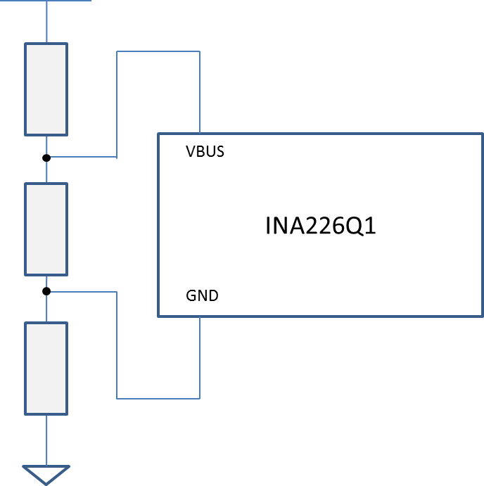
3. Is it possible to measure the differences between VBUS and GND for the following circuit?


4. Can we control the timing of current sensing and voltage sensing using microprocessor?

5. Do you have simulation model whose current sensing timing and voltage sensing timing can be controled.

6. Do you have a spec information of input time constant?
    Do you have any information of input capacitance and input resistance?

We appreciate your help.

Best Regards

  • Hi na na78,

    Find my answers below:

    1.  

    2. I have not used the INA in this configuration before, so I can't really make a statement but I believe that at least the CMRR will shift.

    3. I apologize but I don't undertand the diagram. It is 3 shunts, 3 loads, 2 loads and a shunt? I am not sure what your boxes represent. Also, the Vin+ and Vin- connections are not there not sure what configuration you are trying to achieve. You can't certainly connect GND to that point between "loads".

    4. There is an internal clock that you can't control. You can do single shot but you can't synchronize with internal clock.

    5. No, we don't have any. We do have the INA226EVM (includes hardware + software).

    6. From the 3 we have the input capacitance = 3 pF.

    Hope this helps!


  • Hi Mayrim

    Thank you for your reply.
    Could you please check the following?

    1. We got the gain error. Can we refer the offset errors?

    2. Thanks. We got it.

    3. We have to apologize for our confusing figure. We supposed 2 loads and a shunt. Anyway, we wanted to know the difference of voltage between VBUS and GND could be measured even if GND pin was not connected to ground. That is impossible, isn't it?

    4. Shunt current and bus voltage is sampled by ADC automatically and that can not be controlled, isn't it?

    5. Thanks. We got it.

    6. Is the capacitance 3 pF you mentioned the input capacitance of ADC? Do you have the information about input impedance?

    Please let us add one more question.

    7. Can we select the any Rshunt so that the input voltage of INA226 is in the shunt voltage input range?

    8. The specifications on the datasheet are described for Vvs=3.3V. If Vvs=5V, are there any considerations?

    9. Can we refer the maximum value of Input bias current over temperature?

    10. What is the voltage source for generating the reference voltage of ADC, Vbus or Vvs? We are assuming the Vbus is open.

    Best Regards
  • We close this thread because we started new one.

    e2e.ti.com/.../515199

    BestRegards