This thread has been locked.

If you have a related question, please click the "Ask a related question" button in the top right corner. The newly created question will be automatically linked to this question.

INA225: Step Response

Part Number: INA225

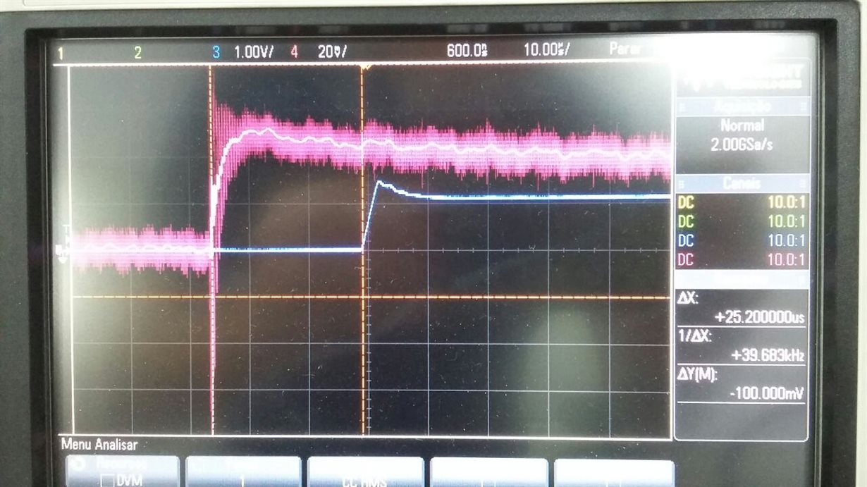
Hello, my current control system, using a INA225AIDGKT with a 100V/V gain, is failling due to a step response delay near 25us, as is possible to see at attached picture. The magenta probe was directly on pins 1 and 8, and the blue probe on in 4, that isn't connect to external circuits or loads. The expected signal is the same of fig.24 from datasheet. What could be happening ?

Ricardo Urio


  • Dear Ricardo, 

    this does seem awkward, indeed. Could you give me any more specifics into your testing? So you are seeing this when the device is isolated from any external circuitry (i.e., just the device, supplies, and oscilloscope)? Is this an EVM you are testing on, or your own PCB? 

    I will set up an INA225EVM and perform the same test on my end to see what I come up with and follow up with you shortly.

  • Could you give me any more specifics into your testing ?

    A: The current is applied on a resistor.

    So you are seeing this when the device is isolated from any external circuitry (i.e., just the device, supplies, and oscilloscope)?

    A: Not totally, only output is isolated

    Is this an EVM you are testing on, or your own PCB?

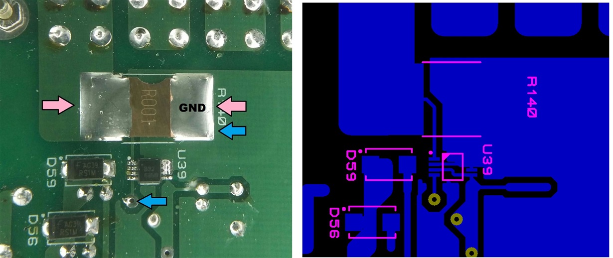
    A: I'm using my PCB.  The picture shows the probe connections and partial layout.

    Ricardo Urio

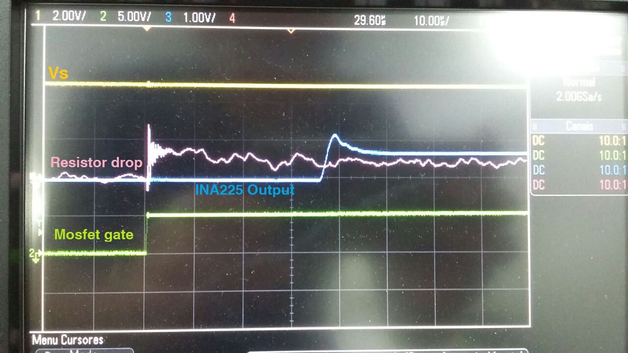
  • One more picture showing Vs, resistor drop, INA225 output and mosfet trigger. All probes referenced to INA225 ground, directly on pin 02. Resistor drop signal was filtered due to high noise.

  • Dear Ricardo,

    After having a look at your setup and checking the part in the lab, here is what I have found for you:

    It looks like the issue you are having is the output of the part is saturating against the ground. The figure in the datasheet you are attempting to replicate was captured with a Vcm of 12V, and more importantly in this case, a reference voltage of Vs/2. With your output referenced at ground, the part at startup is requiring that 25us to recover off the ground into its linear dynamic range. A good way to see this for yourself, if you have a second supply, is to stack them, provide one supply with a static minor voltage (I used 1mV), and then toggle your 20mV on and off to trigger your scope and see the improvement in response time. I found at about the 2mV mark, the response time was almost that of the datasheet. 

    Ultimately, I don't know the specifics of your control system, but as long as the system does not go open loop (Vout = 0V), once you get beyond the momentary startup, you shouldn't have an issue. If you ARE worried about that, a small voltage applied to Vref should life the output off the ground enough that you operate closer to the datasheet spec.

    Hope this helps.

  • Hi Carolus, you're right ! With a small positive Vref I got the expected response. The offset generated is not a problem and I can solve within microcontroller program. Maybe is there some datasheet information that shows this INA225 characteristic ? Anyway, thank you and congratulations by your fast and assertive answer.