This thread has been locked.

If you have a related question, please click the "Ask a related question" button in the top right corner. The newly created question will be automatically linked to this question.

About LM675 (for non-inverting operation )

Other Parts Discussed in Thread: LM675, OPA549, OPA548, OPA564

Dear Sirs

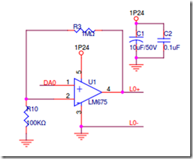
I use  LM675 for non-inverting operation.

The circuit is shown as follow:

The input voltage DA0 (pin1) is 0V.

But the output pin (pin4 L0+) is 22.8V.

And the pin 2 is 2.1V.

But when I change the op from LM675  to L165 (ST part).L165-3A-OP.PDF

The circuit goes well.

Could you help me? thanks

Thank you very much

BRS

Nat

  • Hello Nat,

    The LM675 is not really designed to be operated single supply. It is NOT a rail to rail device - either on the input or the output.

    The input range does not include Ground. The input stage needs "footroom" and "headroom" for the internal current sources and mirrors.

    The inputs need to be at least 3V from each rail, so the "legal" input range for your circuit is +3V to +21V. This is specified in the "Input Common Mode Range" specification in the datasheet (the spec is for split supplies, which is a ± number, so 25V - 22V = 3V for both positive and negative).

    If the internal schematics for both are accurate, the L165 has a input stage that is a bit more "forgiving", but can still fail. While it still seems to 'work", you may see that the offset voltage is worse and you may find other issues (if it heats up). The L165 does not have a common mode specification - as it is also designed for split (±V) supplies.

    You want to look at high power amps like OPA548,OPA549 and OPA564. They have a common mode voltage to GND, so they can be operated single supply and will not have a problem with the 0-10V input.

    Regards,