This thread has been locked.

If you have a related question, please click the "Ask a related question" button in the top right corner. The newly created question will be automatically linked to this question.

max value of feedback resistor for hysteresis in TLV3701 (to keep input current draw to a minimum)

Other Parts Discussed in Thread: TLV3701, TINA-TI, TLV3691

Hi,

I am trying to obtain 20~30mV hysteresis in the TLV3701 comparator with minimal current draw at the non-inverting input.

Input voltage is applied to a resistor R1 connected to the non-inverting terminal.  Ref. voltage is on the inverting terminal.  Let R2 be the feedback resistor for hysteresis between the non-inverting input and output terminals.

How do I determine or choose the maximum allowed value of R2 to get me the 30mV of hysteresis without significantly loading the input source, which is very sensitive to current load.  The input voltage source is obtained as the tap voltage of a resistive divider whose tap point is connected to R1.

I tried using R2 = 10Megohm with R1= 30k - 60k ohm, but that gives me 0.6V of hysteresis instead of 30mV.

I  have seen standard equations to determine hysteresis, but they don't describe how to arrive at the max R2 value for a given comparator.

Are there equations for me to determine the max allowed value of R2 for the TLV3701 comparator?  I would like to keep the current draw from the input voltage source (including the current through the resistor divider) to < 5uA.

Regards,

Nitish

Let R1 be the resistor between the input and the non-inverting terminal.Input voltage is obtained using a voltage divider from a battI would like to keep the 

  • Hello Nitish,

    I am missing some of the details of your comparator circuit such as the supply and reference voltages, but the R1 and R2 values designated in your circuit should have set the hysteresis close to the 20 to 30 mV you were after - not 600 mV. Something else must have been mis-set. Also, do realize that most of the operating current in the circuit is going to the reference voltage divider so the sum of the two resistances must be selected to to keep the current under 5 uA.

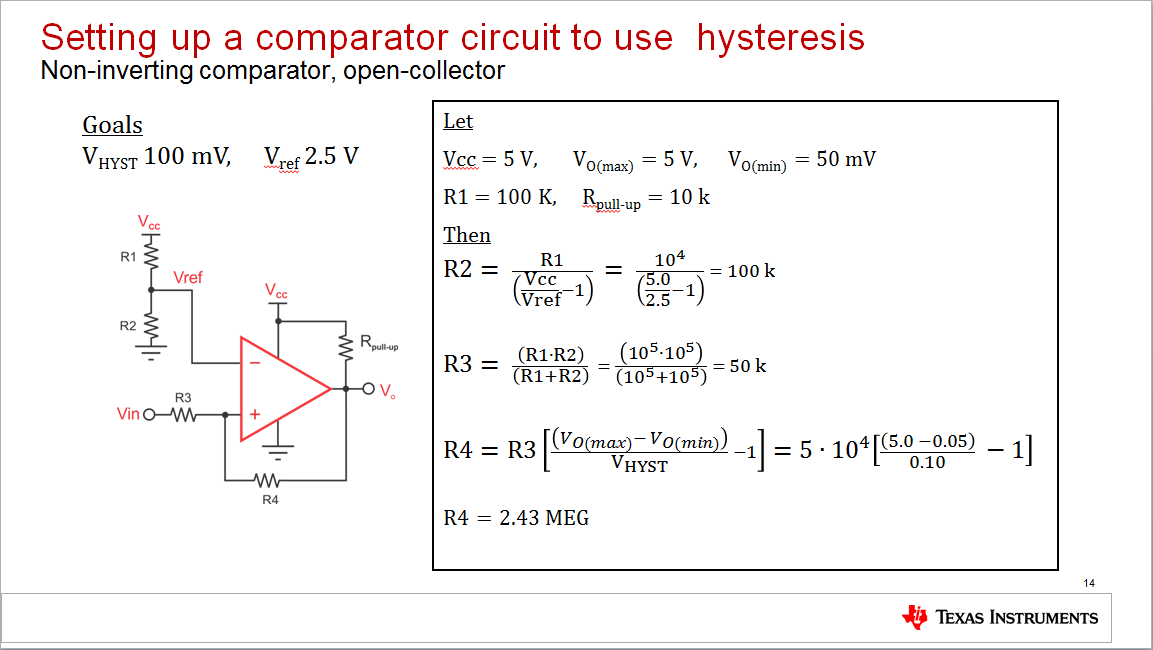
    Here is an image from a slide I prepared previuosly showing how to calculate the resistances that will produce the desired hysteresis in a non-inverting comparator circuit. Note that these equations will work for a push-pull output comparator such as the TLV3701 as well. I just use Vo(max) and Vo(min) 50 mV from the supply and ground rails for the push-pull output; 4.95 V and 50 mV.


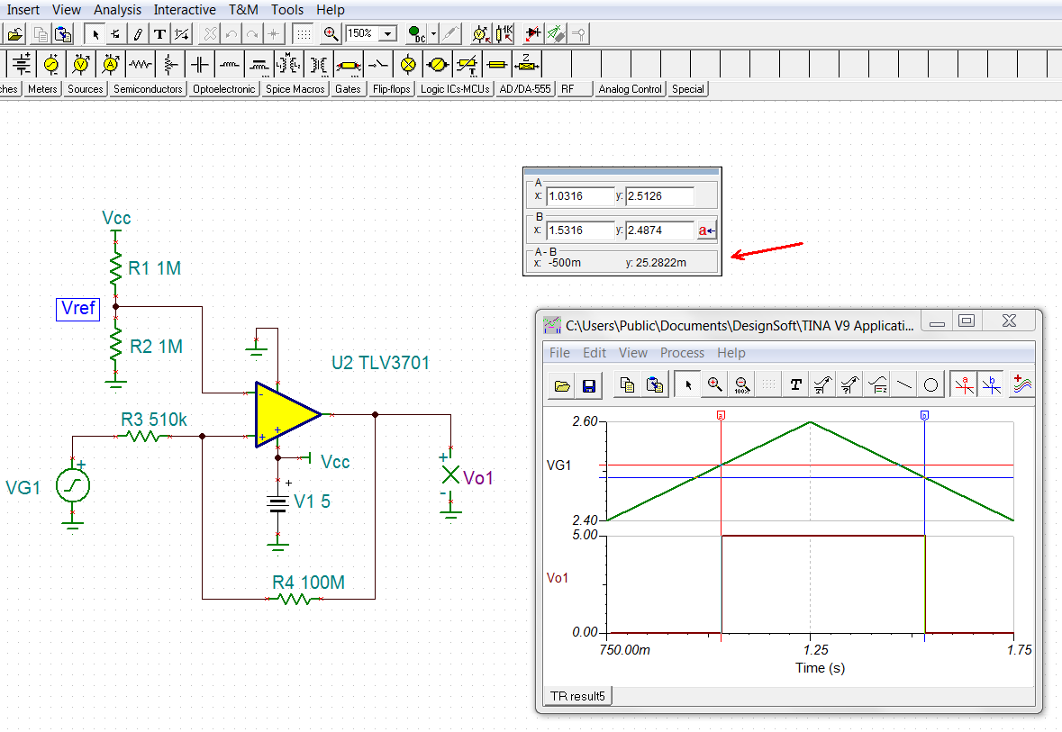
    I then applieded the above equations to set up a hysteresis of 25 mV for your circuit. Since I didn' know your Vcc and VREF settings I used 5 V, and 2.5 V, respectively. To keep the current low through R1 and R2 the divider resistors I made them each 1 Megohm. The current would then be 2.5 uA through that path. R3 then calculates at 500 k, and 510 k is standard 5 % value. R4 calculates at 100 Megohm based on R3 and a swing 50 mV from each supply rail. I then set the TLV3701 circuit up in TINA Spice to check the resulting hysteresis. The simulation indicates about 25.3 mV which is very close to the desired 25 mV.

    Note that you can select a value for R4 the hysteresis resistor and then solve for R3 the input resistor. Then, the divider resistors R1 and R2 can be determined based on the VREF requirement, and the R3 constraint that their parallel combination is equal to its value.

    Regards, Thomas

    PA - Linear Applications Engineering

  • Hi Nitish,

    The TINA simulation was somehow lost in my previous post. Here it is:

    Regards, Thomas

    PA - Linear Applications Engineering

  • Hi Thomas,
    Thanks for your response. Your assumption about Vref=2.5V was correct. My Vcc value is 4.1V instead. Would you mind doing the simulation with a 250k load at the comparator output (I notice that the output is open in your simulation). I would be interested to know if your equations are valid in the presence of load.

    I figured out why I was observing a larger hysteresis: The MOSFET I was driving (at the output of comparator) had a 4uA gate to source leakage current (once Vgs was around 3.5V), which made R4 appear to be smaller than the 10Mohm value I was using. Once I added a 1Mohm resistor between the output of TLV3701 and the MOSFET gate, the hysteresis band became about ~20mV.

    However, before I was able to get the above result, I had to lower the voltage divider resistors (R1, R2) from their original Mohm type values (I was using in the range of 5-10Mohm) to couple hundred kohm. If I did not do that, the voltage divider was not dividing the voltage properly....my guess is that it was getting loaded by the comparator and the 10Mohm feedback resistor (R4) and the MOSFET at its output.

    Best regards,
    Nitish
  • Hello Nitish,

    I have attached a TINA-TI simulation file in this post that contains the circuit Thomas provided (plus a load resistor) in his previous post. This way you can simulate and see how making changes to the circuit will effect the performance of the circuit.

    -Tim Claycomb

    TLV3701 with hysteresis.TSC

  • Hi Tim,
    Thanks for sending the simulation. Can you point me to expressions that allow me to calculate hysteresis with various loads at comparator output?
    Regards,
    Nitish
  • Hi Nitish,

    I do not think the hysteresis should change with a load on the output.

    Many of our comparator datasheets, such as TLV3691, provide equations to calculate the desired hysteresis. We also have a Comparator with Hysteresis Reference Design that discusses how to design a comparator circuit to have hysteresis.

    Thank you,

    Tim Claycomb