This thread has been locked.

If you have a related question, please click the "Ask a related question" button in the top right corner. The newly created question will be automatically linked to this question.

LM2903-Q1: LM2903-Q1 output issue

Part Number: LM2903-Q1
Other Parts Discussed in Thread: LM2903

Dear sir

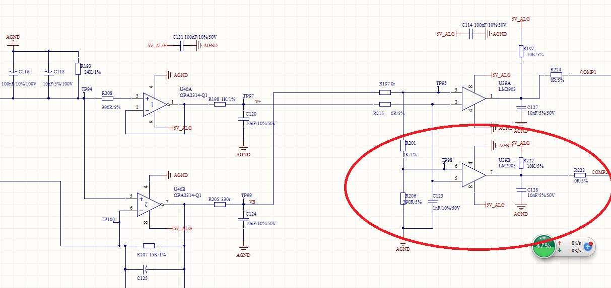
I use LM2903-Q1 in a new project. There is something that i think is unnormal .

Testing process & data

LM2903      PIN 5 (IN+)        PIN6(IN-)           PIN7(OUT)

Votage:         682mv                690mv                 149.5mv

                       685mv                690mv                  200mv

                       687mv                690mv                  1.2v

                       689mv                690mv                  1.85V

                       692mv                690mv                   2.36v

                       694mv                690mv                   2.74v

                       696mv                690mv                   3.26v

                       698mv                690mv                    3.8v

                       700mv                690mv                    4.8v

As the test result, i had some questions:

1,Why does it output: 1.2v 1.85v 2.36v....?The out put always 0V or  5V,isn't it?

2,If the output is between 1V-3V ,how can the MCU recognition the output votage as High level or Low level?

3,If the output data is unnormal,could you please give me some proposal to resolve it? I had try to decrease C128 to 10pf    or     remove C128     or    crease R222 to 20K,  the result had not improve.

Please reference below SCH. 

Thank you!

  • Hello Bin,

    Please allow us time to look into this, and we apologize for any delays during the holiday season here in the US.
    Please know that we are working on this and will get back to you with more information.

    Best,
    Michael
  • Hello Bin,

    Here is another E2E post that had a similar question:
    e2e.ti.com/.../448261

    Are you measuring your output voltage with a bench top or handheld multimeter? If so, it may be averaging a high number of switching transitions which is showing a voltage in between the two levels.

    If you measure the response on an oscilloscope do you see a DC voltage or a switching voltage level? Please feel free to share scope shots or additional information you have.

    Best,
    Michael
  • Dear Michael
    Thank you for your reply!
    i measured it which handheld multimeter. As you said "averaging a high number of switching transitions showing a voltage in between the two levels ",i had some questions:
    1, Which switchs ? inside LM2903 or handheld multimeter internal switchs?
    2,Why does other locations which we had used LM2903 hadn't this issue?

    Thank you !
  • Bin,

    Instead of using a DMM to measure pin 7 OUT, use an oscilloscope.
    There is is no hysteresis implemented in the design.
    Therefore it is possible that the output could oscillate when the input difference signal is small.

    If there is oscillation, look for coupling between pins 6 & 7 (like parallel traces)
    Also check R206 GND trace to make sure it doesn't couple with pin 4 or C128
  • Hi Ronald
    It is an exciting news that I found the reason.
    As i use an oscilloscope measure the input and output, i found when the voltage difference between pin2 to pin 3 is too small ,the output voltage is a square signal. Please refence below:
    PIN2(IN-) PIN3(IN+) PIN2-PIN3 Output
    Voltage(V): 2.1031 2.1026 0.0005 square wave
    2.0977 2.1010 -0.0033 square wave
    2.0922 2.0994 -0.0072 5V
    Is it because the accuracy of LM2903 is not enough? And what will we do can make the output normal?
  • Bin,

    The reason is LM2903 has a lot of voltage gain and no internal hysteresis. If there is enough coupling between pin 7 and 6 and impedance on pin 6 node is too high then oscillation is possible.  

    The 390 ohms on pin 6 node is not too high, so I suspect high coupling between traces on pin 7 & 6. Board layout is a likely factor.

    Adding hysteresis can also fix, try add 200k resistor between pins 5 and 7. This will add about 10mV of hysteresis