This thread has been locked.

If you have a related question, please click the "Ask a related question" button in the top right corner. The newly created question will be automatically linked to this question.

Micro volt amplification

Other Parts Discussed in Thread: INA826, OPA188

I am trying to use a gas sensor. It is a chemi-resistor. Its resistance changes when it comes in contact with any of the gas. I want to read the voltage change when the sensor comes into contact with the UV light. The voltage change is in order of 50 micro volt. Which amplifier should I use so that the micro-controller can read this change? 

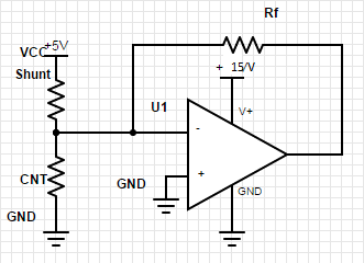
This is my circuit, CNT is the carbon nano tube gas sensor. I am measuring the current across the shunt, the same current will be flowing across the CNT. Opamp out will give me the voltage across the CNT and using ohms law I can measure the CNT resistance. 

Please help me with the amplifier circuit.

  • Hello Hardik,

    I do find an issue with the circuit you have shown. The voltage divider created by the shunt resistor and the CNT will result in a positive voltage being applied to the inverting input of the op amp. This will cause the op amp output to try and move to a negative voltage level. But because the op amp negative power supply rail is set to GND level, the output won't be able to move to a negative level. If that is the intention, then the op amp negative power supply pin would need to be powered from a negative supply voltage. More effort would be required to create a satisfactory single op amp CNT solution.

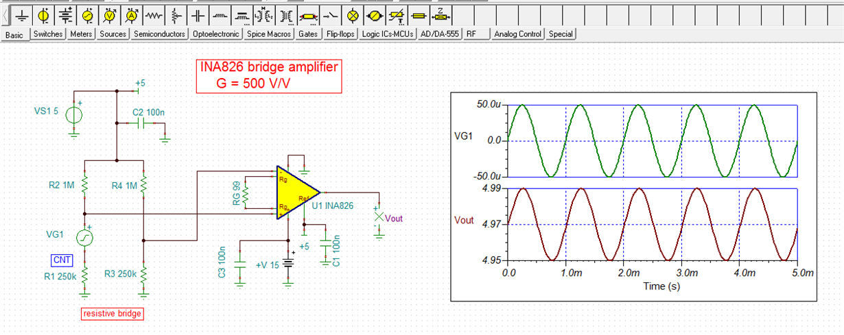
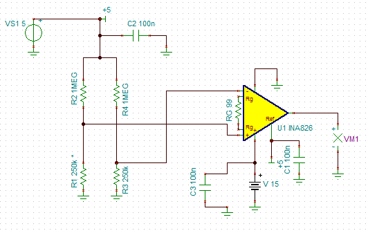
    A single op amp circuit may not be the best approach for satisfying this application. I suggest setting up the CNT resistor in a conventional 4-resistor bridge circuit and following it with an instrumentation amplifier. You can see an example below in the TINA schematic. I wasn't able to find any information about the CNT resistor characteristics so I just used convenient values to demonstrate the idea. Using the instrumentation amplifier approach allows for a more straightforward design that provides easily settable gain, high gain accuracy, high common-mode rejection, and application flexibility. 

    Do note that you are working with a very small voltage change at the instrument amplifier input (50 uV) and even with a gain of 500 V/V, that only yields an output voltage change of about 25 mV. Therefore, an additional gain stage will likely be needed after the instrumentation amplifier stage.

    Regards, Thomas

    Precision Amplifiers Applications Engineering

  • Thank you, Thomas, for your reply. So, I need to put the Vout of the instrumentation amplifier to one more amplifier? Should I use one more instrumentation amplifier?

  • Hello Hardik,

    You could use another instrumentation amplifier to follow the INA826, but that shouldn't be necessary. I would simply follow it with an operational amplifier, connected to the INA826 output. The op amp would be easiest to use if configured as a non-inverting amplifier. The dc reference voltage level established by the voltage applied to the INA826 REF pin would then be the common-mode voltage (VCM) level for the op amp. Often  VCM is often set to a mid-scale level such as 5 V, for a 10 V range, etc. A passive RC low-pass filter could be used between the INA826 output and the operational amplifier input if you want to limit the bandwidth and reduce the noise response. That is often helpful in reducing the unwanted noise at the amplifier chain output.

    Regards, Thomas

    Precision Amplifiers Applications Engineering

  • Thank you, Thomas, can you please suggest me which op-amp IC should I use after the instrumentation amplifier.

  • Hello Hardik,

    The op amp should have low offset and low offset drift, and be usable with the +15 V single supply. Take a look at the OPA188. I think it will do what you need:

    Regards, Thomas

    Precision Amplifiers Applications Engineering

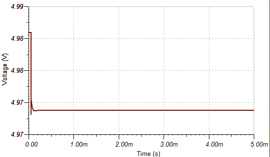
  • Thank you, Thomas, for your help. I have one more doubt. Can you please tell me what should be the output of the circuit(that you have provided me) when the wheatstone bridge is in the balanced state? I am getting 4.97 V as the output.

  • Hello Hardik,

    Ideally, when the bridge is perfectly balanced the differential voltage across the INA826 inputs is 0 V. The output voltage then would be equal to the voltage level applied to the Ref pin. If that level is exactly 5 V, then the output would be 5 V. Once the differential voltage chages due to a bridge imbalance, the output voltage moves up or down, relative to the Ref voltage.

    Any amplifer is not perfect and will have what is referred to as input voltage offset (Vosi). The INA826 is specified with a typical Vosi of +/-40 uV, and a maximum of +/-150 uV, at an ambient temperature of 25C. Also, there is an output stage voltage offset  (Voso) rated at +/-200 uV typical, and +/-700 uV maximum, for an instrumentation amplifier of this variety. The two offset errors combined produce a dc error that is a function of the instrumentation amplifier's gain setting. Note 1, below the Electrical Characteristics table in the datasheet Section 7.5, lists the total offset error as:

    (1) Total offset, referred-to-input (RTI): VOS = (VOSI) + (VOSO / G)

    The TINA INA826 simulation has preset Vosi and Voso levels built in and that is why the simulation produces a level that isn't the ideal 5 V level, with the bridge balanced.

    Note that the above total offset is referred-to-input. The offset that will been seen at the INA826 output will be gained up by the 500 V/V gain. Therefore, it is easy to incur a 30 mV output offset in such a high gain setting, even though Vosi and Voso are well within their datasheet ranges.

    Regards, Thomas

    Precision Amplifiers Applications Engineering 

  • Thank you, Thomas. I appreciate your help.

  • Hello Thomas, I have one more doubt regarding the circuit. Can I reduce the Vref (reference voltage)? Actually, I have to read the circuit output on a microcontroller pin. So if the output is greater than 5V it will cause problems. I need to get this output in range so that the microcontroller can read it.