This thread has been locked.

If you have a related question, please click the "Ask a related question" button in the top right corner. The newly created question will be automatically linked to this question.

UAF42: Problem with UAF42AP band pass filter generating unwanted signal at its center frequency

Part Number: UAF42
Other Parts Discussed in Thread: LMC7660

Hello,

I have designed a band pass filter using part UAF42AP at f = 500 HZ (See my circuit schematics at 1.tiff). The filter is working well and neutralizing unwanted signals at other frequencies. However, while using the spectrum analyzer to evaluate its performance, I noticed that a signal (although weak) is generated by the IC at its center frequency. For example, you can notice this when inputs such as 1 Volts sin 50 Hz (see 3.tiff) or 1 Volts sin 5 KHz (see 2.tiff) were used. In other words, a self generated signal is added/mixed to the signal I am trying to collect at the center frequency, which is problematic. I also found an application data describing how to use UAF42AP to make a sine generator (see sbfa002.pdf). Therefore, I am suspecting that for some reason, maybe me not connecting some of the pins right, this chip is partially performing as an oscillator/sine generator. In addition, the self generated signal at the center frequency is in direct relation with the gain of the filter.

Please advise if any experts can help me resolve this problem. 

On a separate, any suggestions on how to reduce the noise when using UAF42AP would be appreciated as well.

P.S. I am using breadboard for this test. The green signal is the output and yellow is the input.

Best Regards,

sbfa002.pdf1.tiff2.tif

  • Hi again,

    I just noticed I did not upload "3.tiff" in my previous post. I upload it in this one. 

    My apologies,3.tif

  • Hi Kamran,

    It appears my first response to your UAF42 inquiry didn't post. Sorry about that and the delay it caused. I assume you used the Burr-Brown/TI APPLICATION BULLETIN, "FILTER DESIGN PROGRAM FOR THE UAF42 UNIVERSAL ACTIVE FILTER," as a guideline? If so, can you tell me which POLE-PAIR (PP) SUBCIRCUIT you used for the band-pass filter design?

    Additionally, I see your frequency domain measurements. Would it be possible for you to connect a DSO at each of the HP, LP, BP and Vout filter points and see if you can capture an image of the oscillation wherever it may be appearing? It would be helpful to see what it looks like in the time domain.

    Do you have power supply bypass capacitors on the supply pins to ground in your circuit? They need to be in place.

    Regards, Thomas

    Precision Amplifiers Applications Engineering

  • Hi Kamran,

    I just found one problem with your UAF42 BP filter schematic and it may just be the way it is drawn. The 10 kilohm input resistor in the output amplifier stage is connected to the summing junction (pin 14) of the low-pass integrator stage. That isn't correct; the resistor should connect to the Band-pass Out at pin 7.

    I don't know if that will correct the 5 kHz oscillation problem, but it does fix one issue.

    Regards, Thomas

    Precision Amplifiers Applications Engineering

  • input 1mV at 500 Hz real time output BP pin 6.tifinput 1mV at 500 Hz real time output HP pin 13.tifinput 1mV at 500 Hz real time output LP pin 1.tifinput 1V at 5 KHz real time output BP pin 6.tifinput 1V at 5 KHz real time output HP pin 13.tifinput 1V at 5 KHz real time output LP pin 1.tifinput 1V at 50 Hz real time output BP pin 6.tifinput 1V at 50 Hz real time output HP pin 13.tifinput 1V at 50 Hz real time output LP pin 1.tifHi Thomas,

    Thank you or your response.

    -I used the inverting pole-pair

    - You can find the real-time response of the filter with different inputs and LP,HP, and BP in the attached pictures. Please pay attention to scale of every signal in the bottom left of the pictures. As you will note, the unwanted 500 HZ signal shows itself in real-time as well, specifically for the case of 1 Volts sin 50 Hz.

    - Yes, I have used two 100 uf electrolytic capacitors for the + and - supply pins of the filter.

    Best Regards,

  • Hi Thomas,

    You are correct. I drew the sketch wrong. the 10 Kohm resistor is connected between pin 6 and pin7.

    Best Regards,

  • Hello Kamran,

    Then, I don't find anything incorrect about your UAF42 band-pass filter circuit from a schematic standpoint. Usually when that is the case there is something about the circuit construction that is leading to an unexpected oscillation. Do you have an image of your circuit construction you can share? Also, try adding some 100 nF bypass capacitors to the power supply pins. A 47 uF capacitor is a low frequency bypass and may be ineffective at higher frequencies. And you mentioned that you are driving another op amp with the UAF42 output op amp. Can you provide more details about the load?

    Have you tested more than one UAF42 device in your circuit? If so, did you still have the oscillation? I have to ask, did you obtain the UAF42 device you are using from TI directly, or a TI authorized distributor, or from somewhere else? Devices of unknown origin can have problems.

    Regards, Thomas

    Precision Amplifiers Applications Engineering

  • Hi Thomas

    I added the 100 nf ceramic capacitors as you suggested and still no improvement was observed. You can find the picture of the setup I am studying right now. It consists of a LMC7660 voltage regulator in order generate the negative supply and the UAF42. No additional external op amp is being used at this point.

    As I mentioned I have not used the 47 uf, but 100 uf electrolytic capacitors for the bypass. The most significant issue I am having right now is not the high frequency operation. It is the generation of an unwanted signal at 500 Hz, presumably by the UAF42AP. I have purchased the IC from DIGI-key which is a credit distributor and I have used multiple number of UAF42AP ICs and I always encounter the issue I mentioned.

    Best Regards,

    1V at 5 KHz frequency domain.tif1V at 5 KHz time domain.tif

  • Hello Kamran,

    Oh, a white proto board! Certainly this is a quick, convenient way to test a circuit but unfortunately about the worst from signal response and spectral purity standpoints. The board and components are exposed to every possibility problem associated with of a circuit layout and external noise egress.

    I realize that you provided the frequency domain response of the UAF42 band-pass circuit, and it showed peaking around 500 Hz which was assumed to be a low-level oscillation. There was a reason I was asking for a DSO image of the band-pass filter output and Vout. I wanted to make sure that the 500 Hz peaking in the frequency domain was indeed an oscillation. So I request again that you capture the 500 Hz oscillation with the DSO and provide the image.

    The reason I need to see the presence of an actual oscillation is that maybe the 500 Hz peaking is not an oscillation, but instead the noise response of the band-pass filter. The UAF42 universal active filter topology is not know to readily oscillate. If the UAF42 circuit is physically subjected to the open environment of a proto board extraneous noise made up of a wide range of frequencies can be getting in to the circuit. You actually may be observing the noise signature of the filter's band-pass response. Since the filter is tuned to 500 Hz, and there is an addition G = -10 V/V amplifier at the output the noise would be greatest at that frequency. Also, you mention the 50 Hz noise. If your line frequency is 50 Hz the wiring and lights in the room will couple into the open circuit. The line frequency nearly always shows up in the frequency sweeps of even the best laid out audio circuits.

    If you have access to an a closable metal box in which the UAF42 proto board circuit can be enclosed you will almost certainly see the 50 Hz and broadband noises decrease. The power supply wires would need to shielded and bypassed upon entry into the box. A better plan is to power the UAF42 circuit from 9 V volt radio batteries kept inside the shielded box for the test. Once everything is shielded from the and noise ingress reduced look to see if an oscillation is present. 

    Lastly, you are powering the UAF42 from the LMC7660 charge pump, DC-DC converter. Make sure that the oscillator frequency isn't anywhere near 500 Hz. That includes any harmonics. If you find that temporarily powering the UAF42 circuit from the 9 V batteries makes a difference in the frequency domain characteristics, then the charge pump may be generating a frequency related to 500 HZ that is showing up in the output.

    A good, clean PC board layout is key to maximizing analog circuit performance. You may find that the UAF42 circuit performs as expected once the circuit is contained on a well laid out PC board.

    Regards, Thomas

    Precision Amplifiers Applications Engineering

  • Hi Thomas, 

    Thank you for your tips and suggestions.

    I understand the limitations of the breadboard. However, as far as testing a circuit before designing/order the PCB goes, breadboard is the way to go. Do you have a better suggestion on how to test a circuit?

    By the way, I should mention that I saw the same issue when the whole module was implemented on a PCB in a different laboratory/location, although there may have been some negligence when designing the PCB as well.

    Can you tell me what you refer to as "DSO" and I shall perform the test and share the results for you ASAP?

    Regarding the 50 Hz noise, let me clarify that I did NOT mention I have a 50 Hz noise. I only used a 1 Volt Cos (2*pi*50Hz *t) and a 1 Volt Cos (2*pi*5KHz *t) as the input of the filter to evaluate how good it neutralizes the unwanted signals other than at 500 Hz. And it does a good job. However, it adds an unwanted 500 Hz to the system, which I am trying to get rid of.

    I am pretty sure that the issue is not coming from the DC-DC converter, since when I use it for a simple inverting opamp, I do not see that oscillation at 500 Hz, on the SAME breadboard. I also tried using the 9V radio batteries you suggested. no improvement still.

    Best Regards,

  • Hi Kamran,

    "However, it adds an unwanted 500 Hz to the system, which I am trying to get rid of." I find it perplexing that the UAF42 filter appears to be functioning correctly, but is adding a 500 Hz signal on its own.

    By DSO I mean a digital storage oscilloscope. I suggest a 10x probe to reduce the loading the probe adds to the circuit. Make sure the UAF42 circuit's 50 k input resistor is grounded for the measurement. I am looking for an image of the oscillation so that I can get an idea about its characteristics.

    Okay, regarding the 50 Hz noise. My misunderstanding. 

    Let's see what the DSO results look like before I make any other suggestions.

    Regards, Thomas

    Precision Amplifiers Applications Engineering

  • Hi Thomas,

    "I realize that you provided the frequency domain response of the UAF42 band-pass circuit, and it showed peaking around 500 Hz which was assumed to be a low-level oscillation. There was a reason I was asking for a DSO image of the band-pass filter output and Vout. I wanted to make sure that the 500 Hz peaking in the frequency domain was indeed an oscillation. So I request again that you capture the 500 Hz oscillation with the DSO and provide the image.

    The reason I need to see the presence of an actual oscillation is that maybe the 500 Hz peaking is not an oscillation, but instead the noise response of the band-pass filter."

    All the real time images I shared with you were taken with a DSO. Could you please specifically let me know what input (voltage and frequency) do you want me to use as the input and which pins do you want me to read the signal from in order for you to see the possible oscillation?

    "Make sure the UAF42 circuit's 50 k input resistor is grounded for the measurement."

    By grounded,do you mean I have to remove it? The 50K resistor is supposed to be series between the input signal and input of filter according to the datasheet for inverting pole pair configuration.

  • Hi Kamran,

    The original .tif sweep your provided (seen below) has frequency on the horizontal axis and amplitude on the vertical axis. Modern DSOs often provide an FFT mode where amplitude vs. frequency such as this may be obtained. What I am looking for is the common amplitude on the vertical scale, time on the horizontal scale image. Simply a sine wave or whatever wave it is, with time on the X axis. The most common mode of operation and display for an analog or digital oscilloscope. Like:

     When you attempt to capture the waveforms at UAF42 pin 6 and 7 outputs, the circuit input point at the rightmost end of the 50 k resistor that connects to UAF42, pin 12 needs to be grounded. You don't need to provide an input stimulus because if the UAF42 is oscillating at 500 Hz that is the only waveform that needs to be captured.

    Regards, Thomas

    Precision Amplifiers Applications Engineering

  • Hi Thomas,

    I am well aware of the real-time plots. I believe the misunderstanding between us started due to the fact that, for some reason, you were not able to see my real-time images :-) I grounded pin 12 and you can see the response of filter at pin 6 with 10 X probe setting in the attached mp4 file. AS you will note, a significant offset (208 mv X 10 ~= 2.08 V) is present at pin6. In addition, it looks like an 500 Hz oscillation is also present. I was not able to see pin7, since the offset was humongously high and I could now use my DSO. Please let me know if you are not able to open the mp4 file.

    Best Regards,

  • Hi Thomas,

    For some reason, I am not able to upload the mp4 file. Could you please share an email address so that I could send it to you?

    Best Regards,

  • Hi Kamran,

    I just finished setting up the UAF42 500 Hz band-pass filter you had shown in your schematic in our lab. I used a white proto board as well. The 500 Hz band-pass response is exactly as predicted and there was no sign whatsoever of oscillation at pin 7 (BP Out), or pin 6 the -10 V/V amplified output from pin 7. I varied the supplies from +/-6 V to +/-15 V, and left the 50 k input resistor float, and in neither case did oscillation occur. There really isn't much else I can do to try and make it oscillate.

    I suspect there is either a problem with the UAF42 device you are evaluating, or some issue with the remainder of the circuit or connection. Have you tried a different UAF42 in the circuit?

    If you would like to take a different approach for the 500 HZ BP filter, a dual op amp can be configured as either a Multiple-feedback, or Sallen-Key second-order active band-pass filter. The main difference compared to the UAF42 is it would require a few more resistors and 4 quality capacitors. If you would like to try that approach I could assist you with synthesizing the filter.

    Regards, Thomas

    Precision Amplifiers Applications Engineering

  • Hi Thomas,

    Thank you for the help.

    When I do the experiment you described here are the results I get on pin 6:

    1- If pin 12 is directly grounded, I get the 500 Hz oscillation added to a very large DC.

    2- If a 50K is connected to pin 12 and open on its other end, I get a 500 Hz oscillation.

    3- If a 50k is connected to pin 12 and grounded on its other end, I get the 500 Hz oscillation.

    I have tested the filter using different brand new chips and I get this issue all the time.

    Also, there is no remainder to my circuit at this point. the output is connected to a probe. So that possiblity is also out of the picture.

    Could you please send me a picture of the board circuit you assembled and your circuit diagram? This is becoming a very puzzling and frustrating issue for me.

    Best Regards,

  • Hello Kamran,

    We are receiving behaviors from our two different UAF42 bench setups. I tested the different pin 12 connections that you listed and I am unable to get the 500 Hz oscillation in any of them. Here are the details:

    1- If pin 12 is directly grounded, I get the 500 Hz oscillation added to a very large DC. - I observe a small dc shift and no oscillation.

    2- If a 50K is connected to pin 12 and open on its other end, I get a 500 Hz oscillation. - No oscillation.

    3- If a 50k is connected to pin 12 and grounded on its other end, I get the 500 Hz oscillation. - No oscillation.

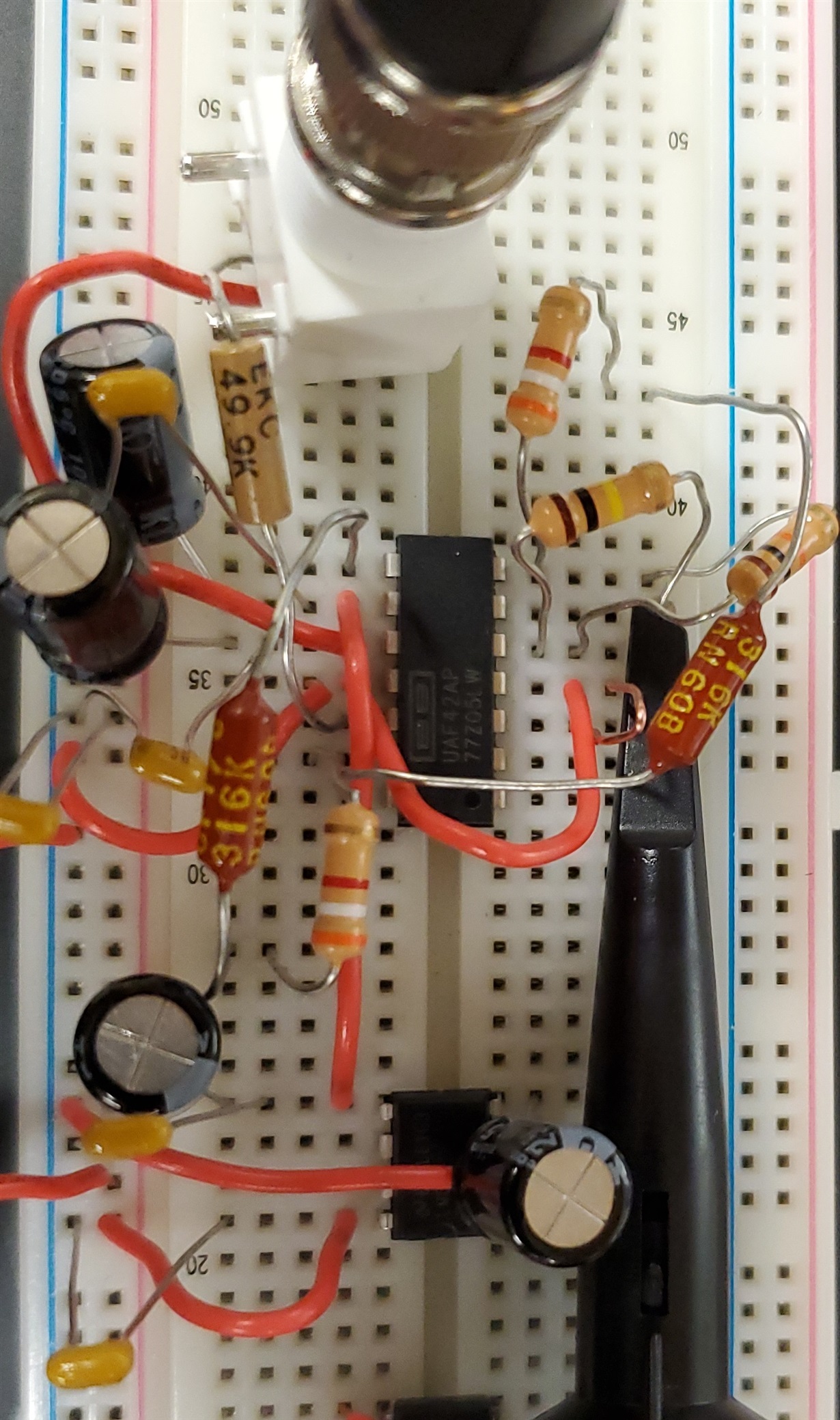
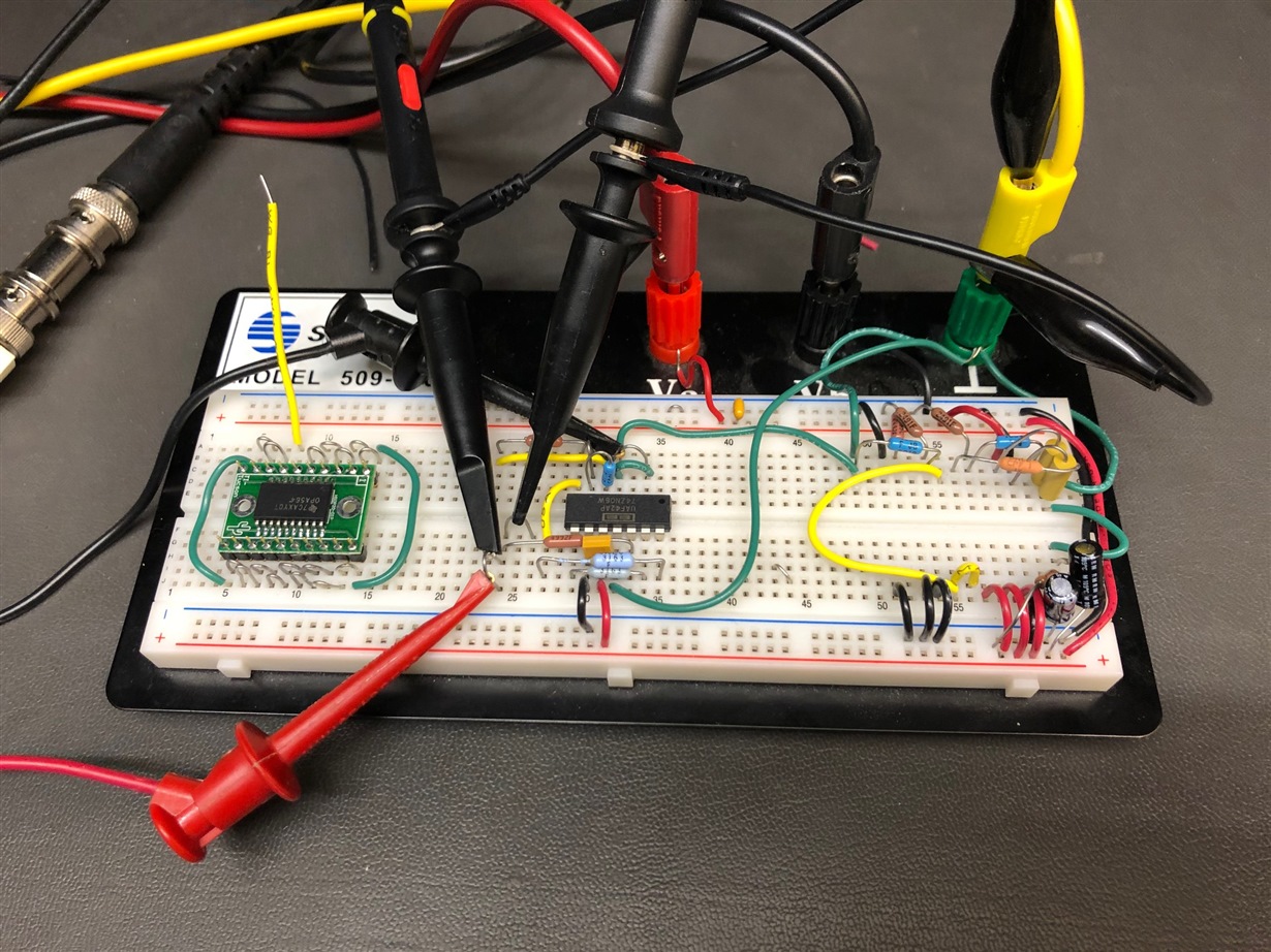
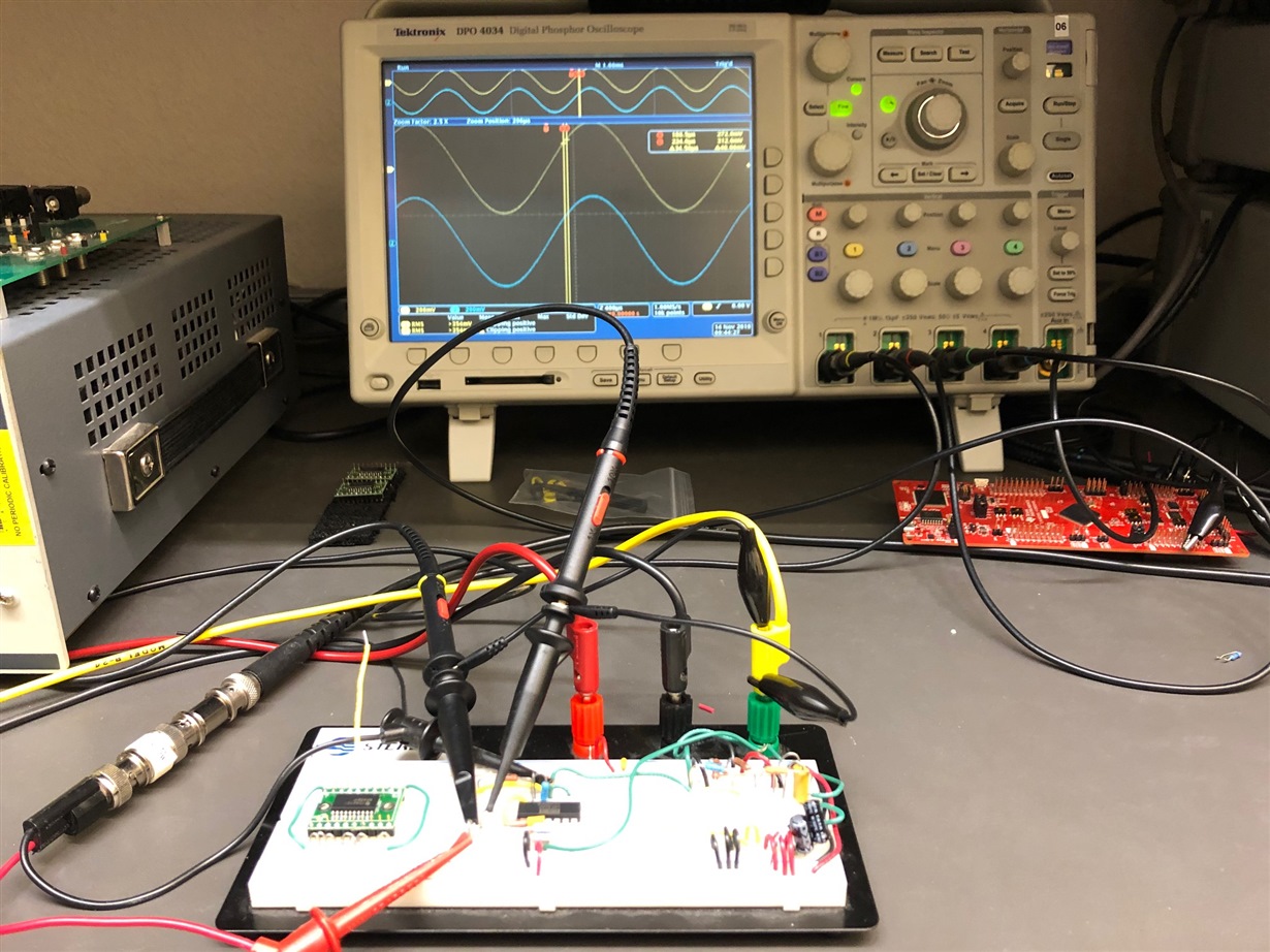
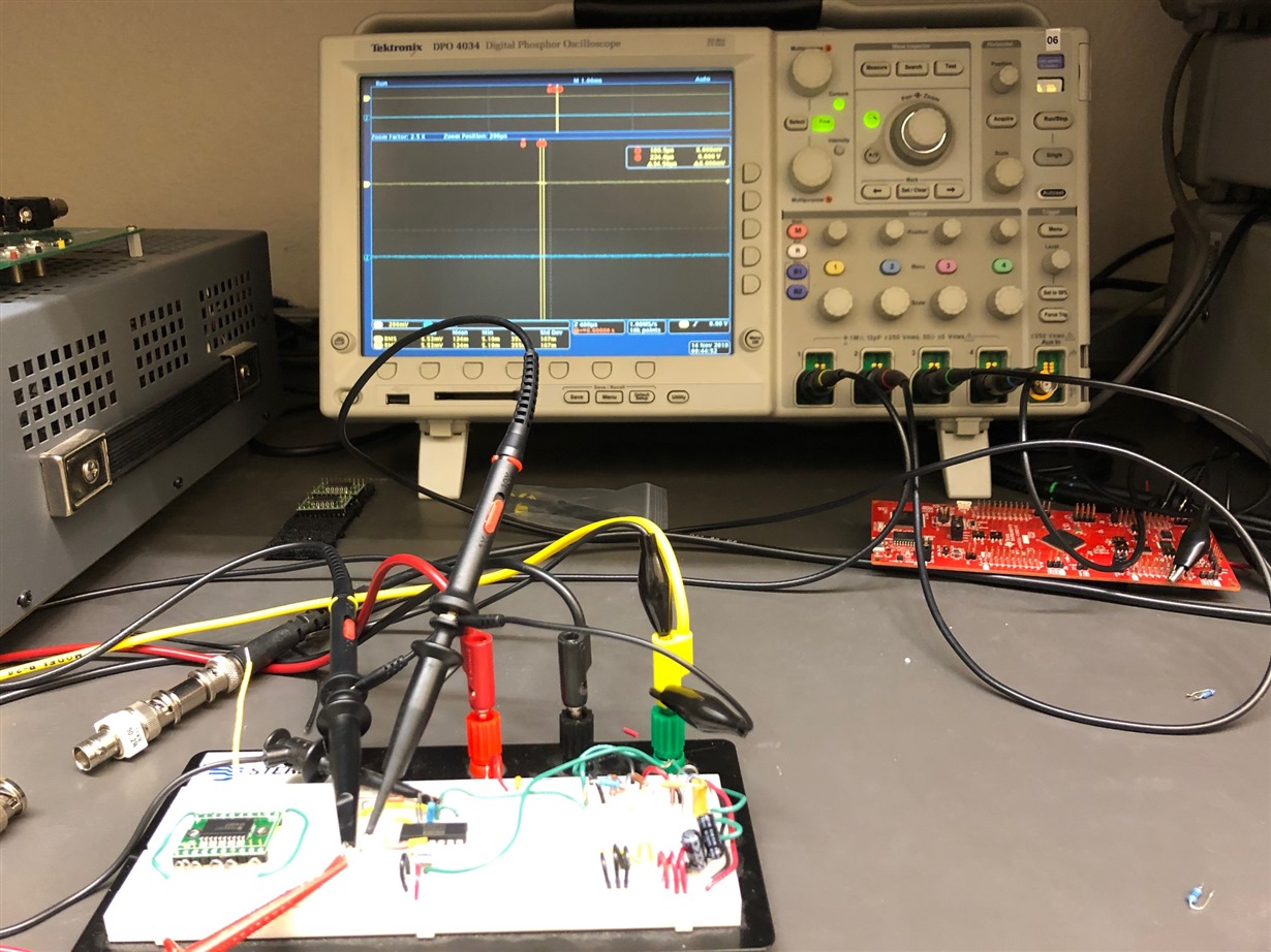
    The first image is the UAF42 white proto board set up. It is less than ideal from a setup standpoint, but probably as non-ideal as yours. There are other components on the protoboard from another circuit, but other than some high capacitance power supply bypass capacitors the rest are not attached to the UAF42 band-pass circuit.

    The next image is that of the UAF42 passing a large signal 500 Hz sine wave from input through to pin 7, BP_out. The amplified output at pin 6 is just as clean except the sine wave is gained up by 10x.

    The last image is the pin 6 BP_out, with the generator connection to the 50 k resistor open i.e. the 50 k resistor input floating. There is no evidence of a 500 Hz oscillation even when the DSO vertical range is set to the lowest 5 mV setting.

    Note that I am using an adjustable lab power supply for V+ and V- which I varied from +/-6 V to +/-15 V. That is a supply difference from the negative charge pump you are using for the negative supply.

    Regards, Thomas

    Precision Amplifiers Applications Engineering

  • Hi Thomas,

    Thanks a lot for sharing the pictures. This is very insightful. I am going to build up my setup exactly like yours. Could you please also send me a quick circuit sketch your circuit including the values for components? I cant read some of them from the pictures.

    Best Regards,

  • Hello Kamran,

    The schematic for the UAF42 circuit that I constructed is shown below. I used 1%, 316 kilohm resistors for RF1 and RF2, because 318 kilohm is not a standard value. It makes a very slight difference in the filter response. 

    I hope this helps!

    Regards, Thomas

    Precision Amplifiers Applications Engineering

  • Hi Thomas,

    I think your pin configuration in the software is not correct, although I think it is just a typo. I finally managed to get rid of the oscillation. But I only get a gain of -5 V/V at pin 6, not -10 V/V.

    I think the problem was that I followed the instructions on the datasheet and assigned RQ to pin 3 in order to increase the Q and gain of the filter, which achieves those goals but adds that oscillation as well and I still do not understand why. So do you have any suggestions regarding how to increase the Q and ABP (bandpass) of the filter? These values are too low with the current configuration.

    Best Regards,

  • Hi Kamran,

    Yes, you are correct. I had made a couple of typos when I was adding the pin numbers to the UAF42 BP circuit. I corrected the drawing as shown here:

    The "Q" of the universal active filter can be increased significantly over what you used in your original design. The steps for designing a particular filter response with the UAF topology are somewhat involved, but can be accomplished if you have the right information.

    The UAF42 datasheet doesn't explain the process, but there is the Burr-Brown Applications Bulletin - sbfa002 that refers the user to an obsolete DOS version of the FilterPro program. I have that DOS program and remember it takes a DOS emulator to run it.

    Alternately, the predecessor to the UAF42 was the UAF41. It provided the same universal active filter function, but its fabrication was based on an earlier technology. The datasheet for the UAF41 went into much detail regarding how to synthesize a particular filter response. I am attaching a copy of the original datasheet, but do note that it is not the best quality datasheet image.

    6607.DSAP0039035.pdf

    I'll attempt to get the UAF42 DOS program to run and if I can that it should make it easy to synthesize a filter having the response you want. If you want to take a crack at getting the program to run I am including the file:

    8308.FILTER42.EXE

    Regards, Thomas

    Precision Amplifiers Applications Engineering


  • Hi Thomas,

    Well, I still do not understand why you ground pin3 and technically use a RQ = infinity for the filter, which would lead to a terrible Q and ABP. But I guess the indirect respond to that is the somewhat incorrect/dishonest representation of the Q and A equations in the datasheet without warning of the self oscillation. For example try a RQ =220 ohm at pin3 and leave pin 2 open like suggested in the datasheet for the inverting configuration. You will get a high Q, but also that unwanted oscillation at your center frequency.

    Anyway, if your circuit design gets rid of the oscillation, which does, I'd appreciate some insight on how to improve the Q and ABP of the filter, since the external RQ setting suggestion in the datasheet is clearly incorrect.

    Best Regards, 

  • Hello Kamran,

    I am confused. I do not see where I have grounded UAF42, pin 3 in my diagram? In actuality, all I have done is simply reproduced your original 500 Hz band-pass circuit. When I compare your circuit to the information in sbfa002, it conforms with configuration PP3 (Fig 9B). I think you will agree that the "Q" is low in this configuration.

    When I read what you have posted above in the first paragraph you use the term "incorrect/dishonest representation." There may be an unintentional error that someone made, but I doubt the intention was to be dishonest. I haven't studied that particular topology to verify your statement, but may do so if time permits.

    I am not able to install a DOS emulator program on my computer due to malware concerns. Therefore, I suggest you see the older UAF41 datasheet I pointed out that has detailed universal active filter synthesis information.

    Regards, Thomas

    Precision Amplifiers Applications Engineering

  • Hi Thomas,

    All I am saying is that, simply add an RQ to pin3 (for instance 220 ohm) and you will note that Q rises as expected by the equations in the datasheet (page 7). However, what is not mentioned is the generation of oscillation at the center frequency. I actually tried several RQ values and noticed that the power of the unwanted oscillation is in reverse relation with the RQ value and that is why when you leave pin 3 open you have not seen any oscillation (RQ = infinity). 

    Doc Nov 18 2019.pdf

    Best Regards,

  • Hello Kamran,

    If you add an external RQ to from UAF42 pin 3 to ground you certainly will affect the "Q" of the filter. Using the datasheet Fig. 2 circuit and setting ALP to 1 V/V results in an RG equal to 50 kilohm. With ALP and RG established the "Q" can be calculated from Eq. 2, in Fig. 2. Applying the values from your original 500 Hz band-pass circuit in the equation, and RQ = 220 Ohms, results in a "Q" of about 75. It may not be readily apparent but a Q of 75 is a very high "Q" that has significant impacts on the filter's peaking, transient behavior and stability. 

    I set the original 500 Hz band-pass circuit up in TINA and added a 220 Ohm RQ from pin 3 to ground. I left the original 50 k R3 in the circuit because 50 k in parallel with 220 Ohms is still about 220 Ohms and it was convenient to do so. You can see the circuit here:

    When I run an ac sweep on the filter you can see that the filter exhibits a high Q behavior especially evident at the 500 Hz band-pass frequency. There is about 36 dB of peaking at the Vbp center frequency (fc) of 504 Hz. When I do a -3 dB check for fl and fh relative to fc I obtain a "Q" of about 79, so very close to the calculated 75.

    Whenever there is peaking in an analog circuit the transient response of the circuit becomes affected; the higher the peaking, the more overshoot and ringing the circuit exhibits. It is a direct indicator of the phase margin of the closed-loop circuit. If the ringing becomes excessive than it may become nearly indistinguishable from oscillation; however it should eventually dampen out if enough time is provided.

    I applied a small-signal step to the input of the high-Q bandpass filter in TINA and observed the following transient behavior for the filter. It is seen here:

    It is evident that once the input step happens it is takes roughly 75 ms for the oscillatory behavior to dampen out. This is completely normal behavior for a 2nd-order system operating with very high Q. In servo control systems they often talk about the damping factor zeta (ζ), where Q = 1/(2ζ) so this would be a very low ζ system. It is also evident that the phase margin of the filter is likely only a degree or two.

    A solution for taming the circuit is to use multiple band-pass stages each having lower Q.

    Regards, Thomas

    Precision Amplifiers Applications Engineering

  • Hi Thomas,

    If this is a completely normal behavior, then it should be mentioned in the datasheet that using any RQ value would lead to significant overshoot in the output of the filter, therefore, making it literally useless. In other words, there is no point in setting the Q value. Please give me one single value of RQ that would improve the Q without introducing considerable overshoot. I tried several from 1K to 50 K and all of them add to that oscillation we are discussing. I also found out that, even Pin 3 being left open, if the input voltage level is increased, the oscillation, again starts becoming significant. try a 1V at 5KHz and see for yourself in the picture below:

    Pic1.tif

    I also tried putting 4 of these filters in series, all of them having pin 3 open and using the auxillary opamp as as buffer, as follows: (The total gain was set at only 10)

    INPUT --> filter --> filter --> amplifier --> filter --> filter --> OUTPUT

    Even with four of these ICs, you will still get the oscillation at 500 HZ (about -75dB). 

    Pic2.tif

    Best Regards,

  • Hello Kamran,

    Raising the Q in a second-order system will increase the overshoot and settling time for a particular filter response type (Butterworth, Chebyshev, etc.). Changing the filter pass-band response from for example a Butterworth, to one having a linear phase response such a Bessel, should improve the transient response characteristics. However, not likely not to the extend that may be required. Additionally, changing response type would affect the amplitude vs frequency characteristics.

    Thank you for your inputs regarding your findings with the UAF42, and thoughts regarding the applications information. It doesn't appear that we are going to come to a satisfactory solution for your application using the UAF42. There may be another product from another resource that more fully satisfies your application requirements.

    Regards, Thomas

    Precision Amplifiers Applications Engineering

  • Hi Thomas,

    You are correct, the performance of this filter is far from what claimed. I really hope our conversation here helps others think twice before buying the UAF42 and save time. What do you recommend to be done with the unused and NotConnected pins for a finalized PCB design?

    Best Regards,

  • Hello Kamran,

    The UAF42 has been and is currently applied in thousands of applications where it capably satisfies the electrical requirements for which it can reasonably achieve. I think it is important to understand the bounds and limitations of any analog circuit, including the universal active filter topology utilized by the UAF42. The requirements for your application dictated a very high circuit Q, which certainly has ramifications in the both the time and frequency domains that need to be fully considered. Even if the solution had been synthesized with a discrete op amp Sallen-Key or Multiple Feedback circuit designed to meet the same criteria the outcome would be the same. It is a normal outcome of a second-order system designed to specific criteria.

    Assuming you were to apply the UAF42 SOIC-16 package that has NC, No Connection pins, the datasheet states on Pg. 2 that NC pins "For best performance connect all NC pins to ground to minimize inter-lead capacitance." If there are any other pins that would not be used, then it would be best to know which ones and then determine if they should be grounded or floated.

    Regards, Thomas

    Precision Amplifiers Applications Engineering