This thread has been locked.

If you have a related question, please click the "Ask a related question" button in the top right corner. The newly created question will be automatically linked to this question.

Oscillation issue on THS4271

Other Parts Discussed in Thread: THS3091, THS4271

Dear sir:

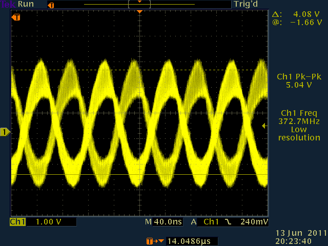
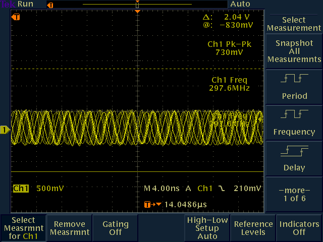
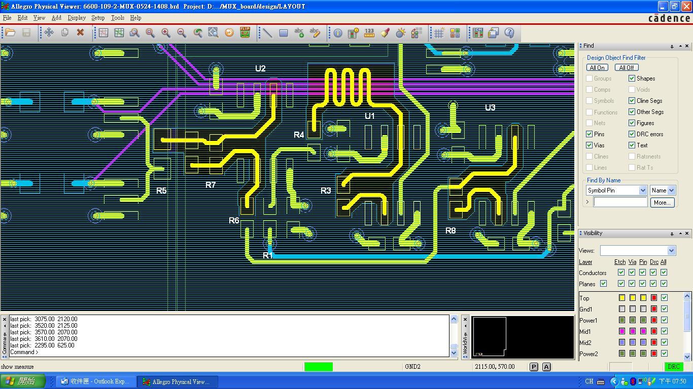
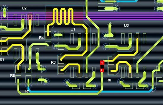
     I got oscillation issue on THS4271. The circuit schematic is as attached. The input is differential sine wave on positive and negative terminals with 10k differential resistor. The output oscillates at 300Mhz or mixed frequency as attached. Once turn off the sine wave SG, the output continue to oscillate. If changing THS3091 with appropriate recommended Rf, the circuit is clean without oscillation. Could someone tell me what's going on with THS4271?
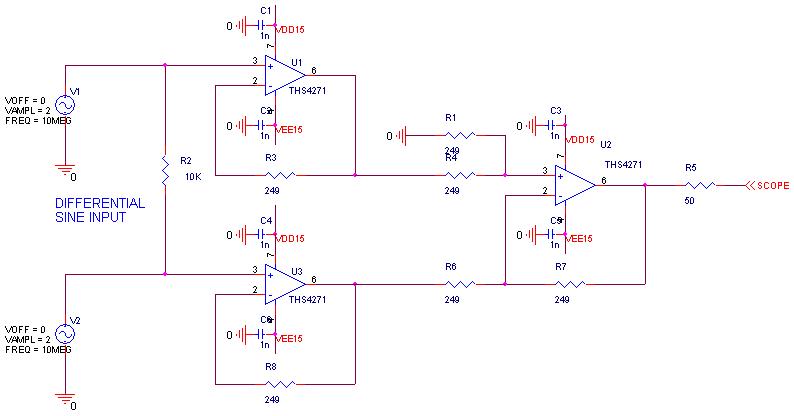
 

Thanks!

Brian

  • Brian,

    Are you using +/-15V (30V total) supplies as your schematic appears to indicate? The THS4271 is only rated for up to 16.5V total supply, so you are exceeding this limit. Does the circuit oscillate if you reduce the supplies to +/-5V or +/-7.5V? If the circuit still oscillates, try isolating the oscillation. Check if the outputs of U1 and U3 show an oscillation.

  • Kristoffer:

        Appreciate for your response!

         Sorry! The power supplies I applied is +-5.5V. Today I did some actions as follows.

    1. When appling +-2VP sinewave in both terminals, U1 dose not oscillate, U3 oscillates.

    2. Try to increase Rf of U3 to 499R, a little bit better but oscillates occasionally.

    3. Shunt Rf (499R) with 3.3pF capacitors, nothing help.

    4. Try to lift pin3, pin2, pin6 of U3 and hard wire to isolate stray capacitance on PCB, it still oscillate. But if touch pin 2 with scope probe,

        The sine wave is pure without oscillation.

    I attached a portion of PCB layout. The ground plane of pin2 & pin6 of all THS4271 are removed to reduce stray capacitance.


    Thanks!

    Brian 


  • Brian,

    Do you have all planes/fills cut out below the input/output pins, or just the layer immediately below the top layer? The best practice is to remove all copper on all layers below the input/output pins

    Would it be possible to cut the trace from the U3 output to R6 to isolate U3 completely? Perhaps the parasitic capacitance of the trace to R6 is causing U3 to oscillate. I suggest cutting the top trace as I've shown in the image below. Cut and remove the trace to form a space for a resistor to be soldered across points 1 and 2 (red boxes).

    By doing this, you can then try a few things:

    1) Test U3 by itself without the trace to R6. Probe the output through a 50ohm series resistor from point 1. Does U3 still oscillate?

    2) Place a 50ohm resistor across points 1-2 and reduce R6 to 200ohm. In this way, there is a 50ohm resistor isolating U3 from the trace.

    Also, have you tried swapping U1 and U3 to check whether the oscillation follows the part or if it depends on the location?

  • Kristoffer:

       Thanks for the response! I did remove the ground plane under the signal between inverting and output node but not for power and other planes. I am afraid there's

    some other issues when I cut off the power planes. I also follow your instruction to probe output through 50 ohm resistance but it doesn't work. I increase R3 and R8 FROM 249K to 499K. It seems OK w/o oscillation.


    Thank you!

    Brian

  • Hi,

    I also am seeing oscillation with a THS4271-based circuit and am wondering how you resolved, or if you did, this issue from back in 2011.

    Ken Aquino

  • Hi! Ken:

        It's been a long time ago. I remembered we increase the loop back resistance from 249 ohm to 499 ohm.

    Brian