This thread has been locked.

If you have a related question, please click the "Ask a related question" button in the top right corner. The newly created question will be automatically linked to this question.

Issue related to THS4130 Eval board

Other Parts Discussed in Thread: THS4130, TINA-TI

Dear TI Community,

I am currently evaluating the THS4130 for one of our application.I have to tune my input signal from 1Hz to 20MHz with voltage input from 0V to 5Vp-p.It seems like we have huge drop in voltage at the output moving from 1Hz to 5Mhz range. We are performing this experiment on THS4130 Eval board only. Readings are given below:

1Vp-p input @8.5KHz  provides 980mVp-p
1Vp-p input @100KHz  provides 970mVp-p
1Vp-p input @500KHz  provides 930mVp-p
1Vp-p input @1000KHz  provides 810mVp-p
1Vp-p input @2000KHz  provides 600mVp-p
1Vp-p input @3000KHz  provides 460mVp-p
1Vp-p input @4000KHz  provides 360mVp-p
Please suggest the way to utilize this differential opamp for our application for above mentioned range

  • Hello,
    Can you please send me some scope pictures as well as a photograph of the board and how it is hooked up.

    Please send me a scope shot at a low frequency (100kHz) and at a high frequency (4 MHz) clearly showing the scope setup (vertical and horizontal settings).

    1. Has the EVM been modified in any way?
    2. Is a transformer being used at the input or the output?
    3. How much quiescent current is being consumed when so ac signal is applied at the input.
    4. Please check each output of the amplifier with a multimeter and no ac signal applied and let me know what each output reads.
    5. What power supply values are being used? Please verify the power-supplies with a meter as well, with no signal being applied.

    I suspect that either the part is faulty or there is an issue with the setup.

    -Samir
  • Hi Sameer,

    Thanks for the quick reply. Please find my inline:

    Can you please send me some scope pictures as well as a photograph of the board and how it is hooked up. 

    Please send me a scope shot at a low frequency (100kHz) and at a high frequency (4 MHz) clearly showing the scope setup (vertical and horizontal settings).
    [Aryam]: Attached in zip file

    Scope_0:1Vp-p input @8.5KHz provides 980mVp-p
    Scope_1:1Vp-p input @100KHz provides 970mVp-p
    Scope_2:1Vp-p input @500KHz provides 930mVp-p
    Scope_3:1Vp-p input @1000KHz provides 810mVp-p
    Scope_4:1Vp-p input @2000KHz provides 600mVp-p
    Scope_5:1Vp-p input @3000KHz provides 460mVp-p
    Scope_6:1Vp-p input @4000KHz provides 360mVp-p


    1. Has the EVM been modified in any way? 

    [Aryam]: No
    2. Is a transformer being used at the input or the output?

    [Aryam]: No
    3. How much quiescent current is being consumed when so ac signal is applied at the input.

    [Aryam]: around 2 mA
    4. Please check each output of the amplifier with a multimeter and no ac signal applied and let me know what each output reads. 

    [Aryam]: Need to verify this
    5. What power supply values are being used? Please verify the power-supplies with a meter as well, with no signal being applied.

    [Aryam]: +- 5V.
    I suspect that either the part is faulty or there is an issue with the setup. 

    I am providing only one single ended input and checking only @ single ended output w.r t  GND.

    2526.Eval Experiment.rar

  • Aryam,
    Something definitely seems off since the quiescent current is 2mA vs. the datasheet typical specification of 12-14 mA. As you mentioned either the part is blown or the setup has some error. Can you replace the part and check?

    Also, please send zip files in a standard *.zip format.

    -Samir
  • Eval Experiment.zipHi Samir,

    We have another Eval-Board which is also behaving the same.Current won't be a issue here as it is responding proper at low frequency.

    I am attaching the wave-forms in *.zip format.

    Regards

    Aryam Gupta

  • Hi Aryam,

    Can you send a schematic of the entire test setup? Have you terminated the unused input? Have you terminated the unused output? Results of single ended measurements can be unpredictable with floating nodes.

    Just because the low frequency response is OK does not mean the circuit is set up properly. If the quiescent supply current is not around 12mA the circuit is not going to operate properly. We need to find the root cause of the supply current anomaly to fix the circuit. Also, make sure the positive supply and negative supply currents are both correct.

    Samir's suggestion to check the DC voltages will be useful because often the amplifier will exhibit strange DC voltages on the inputs and outputs when the supply currents are not correct.

    Regards,
    Loren
  • Hi Loren,

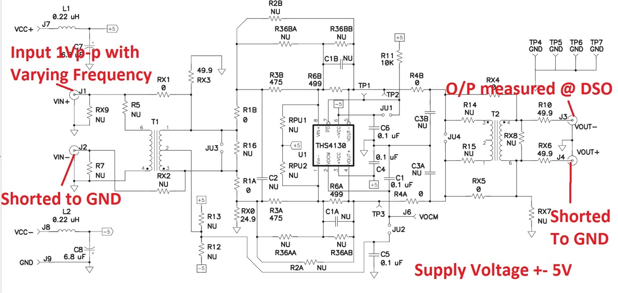
    I am attaching the Image for the scheamtic/setup. Good news is that amplifier is working fine.It was power down via PD pin.And Now we are getting the expected output.Now the quiescent current is also ~13mA.Thanks for your valuable support.

  • Aryam,
    Please see my feedback -
    1. J2 - You do not need to short J2 to GND since the RX2 is open. Also, the correct balanced connection is with Rx0 = 24.9, R3A = 475 and R6A = 499. The reason this is balanced is because on the other side, R3B = 475 and R6B = 499. Also, RX3 = 49.9ohm will be in parallel with the 50-ohm sine source on J1 giving an equivalent 25 ohm to balance Rx0. Does this make sense?

    2. You cannot short one output to GND and measure the other side with a scope. You have a couple of options here -
    BEST - use a differential scope probe.
    GOOD - Use two different channels of a scope terminated in 50-ohm to measure the output. You can use the scope function feature, CH_A - CH_B = differential output.
    OKAY - Terminate J4 with a 50-ohm resistor and just measure the output at J3 with a single-ended scope terminated in 50-ohm.

    -Samir
  • Hi Samir,

    Please find my Inline comments:

    1. J2 - You do not need to short J2 to GND since the RX2 is open. Also, the correct balanced connection is with Rx0 = 24.9, R3A = 475 and R6A = 499. The reason this is balanced is because on the other side, R3B = 475 and R6B = 499. Also, RX3 = 49.9ohm will be in parallel with the 50-ohm sine source on J1 giving an equivalent 25 ohm to balance Rx0. Does this make sense?

    [Aryam]:In my case , I have made RX2 close and Connected J2 to GND. I am only using Single-ended configuration of this differential amplifier.Do we still need to balance?

  • Yes,
    You need to balance. Please use TINA-TI and simulate your circuit.