This thread has been locked.

If you have a related question, please click the "Ask a related question" button in the top right corner. The newly created question will be automatically linked to this question.

Very high spurious levels on channel 2 of TSW54J60 EVM board. This channel uses LMH6401 amplifier

Other Parts Discussed in Thread: LMH6401

Hello,

I see very high spurious levels at low frequencies with channel 2 of TSW54J60 EVM board. This channel uses variable gain amplifier LMH6401.

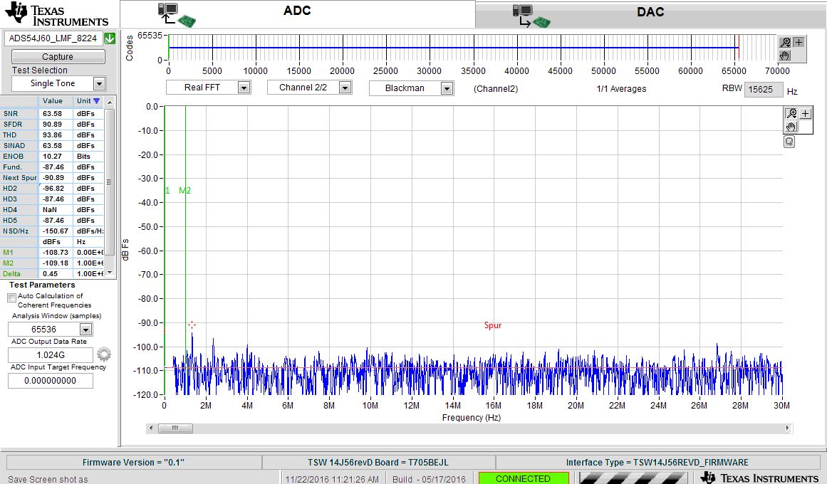
When the gain is at 26 dB, spurious levels are at about 25-30 dB which is very high. 

Please see the figure below.

Please suggest a mod to the board to clean this up.

Thanks,

Mallesh

  • Hi Channamallesh,

    What is the input power and frequency going into the channel 2 of TSW54J60 board for 26dB gain? Or the attached image is just a noise spectrum without any input signal? Are you making sure that the ADC is not being clipped at 26 dB gain. Also, what is the no. of samples on the HSDC pro software you are using?

    Are you using any external filtering at the input source to make sure your source is clean from any spurs?

    Best Regards,

    Rohit

  • Rohit,

    I have terminated input with a 50 Ohm impedance. There is no input signal connected.

    Mallesh
  • Hi Mallesh,

    I can see the low-frequency spur in the capture on my side, and that is due to the input transformer JTX-2-10T on the LMH6401 path. The JTX-2-10T input transfomer is only suitable for frequencies greater than 25-MHz.

    I have attached a capture of the TSW54J60 with the JTX-2-10T transformer removed, and using an external transformer (ZFSCJ-2-4-S+). Even though this transformer is rated for 50-MHz and above, I think it interacts less with the LMH6401 inputs to cause the noise spectrum to increase. The LMH6401 is set for voltage gain of 26dB. I think this does not show the increase in noise spectrum at lower frequencies (attached image).

    The modification that you could do is remove the JTX-2-10T and short across the primary and secondary inputs to provide a differential input path on-board. Then using an external 180' splitter like the ZFSCJ-2-4-S+ or BAL0010 to convert single-ended input source to differential input.

    Best Regards,

    Rohit

  • Rohit,

    Awesome. Thanks a lot for your quick reply.

    Should the external balun have a impedance ratio of 2?

    Please clarify.

    Thanks again,

    Mallesh

  • Mallesh,

    Yes, the external balun should have an impedance ratio of 1:2.

    Best Regards,

    Rohit