This thread has been locked.

If you have a related question, please click the "Ask a related question" button in the top right corner. The newly created question will be automatically linked to this question.

LMH6629: LMH6629

Part Number: LMH6629

Hi,

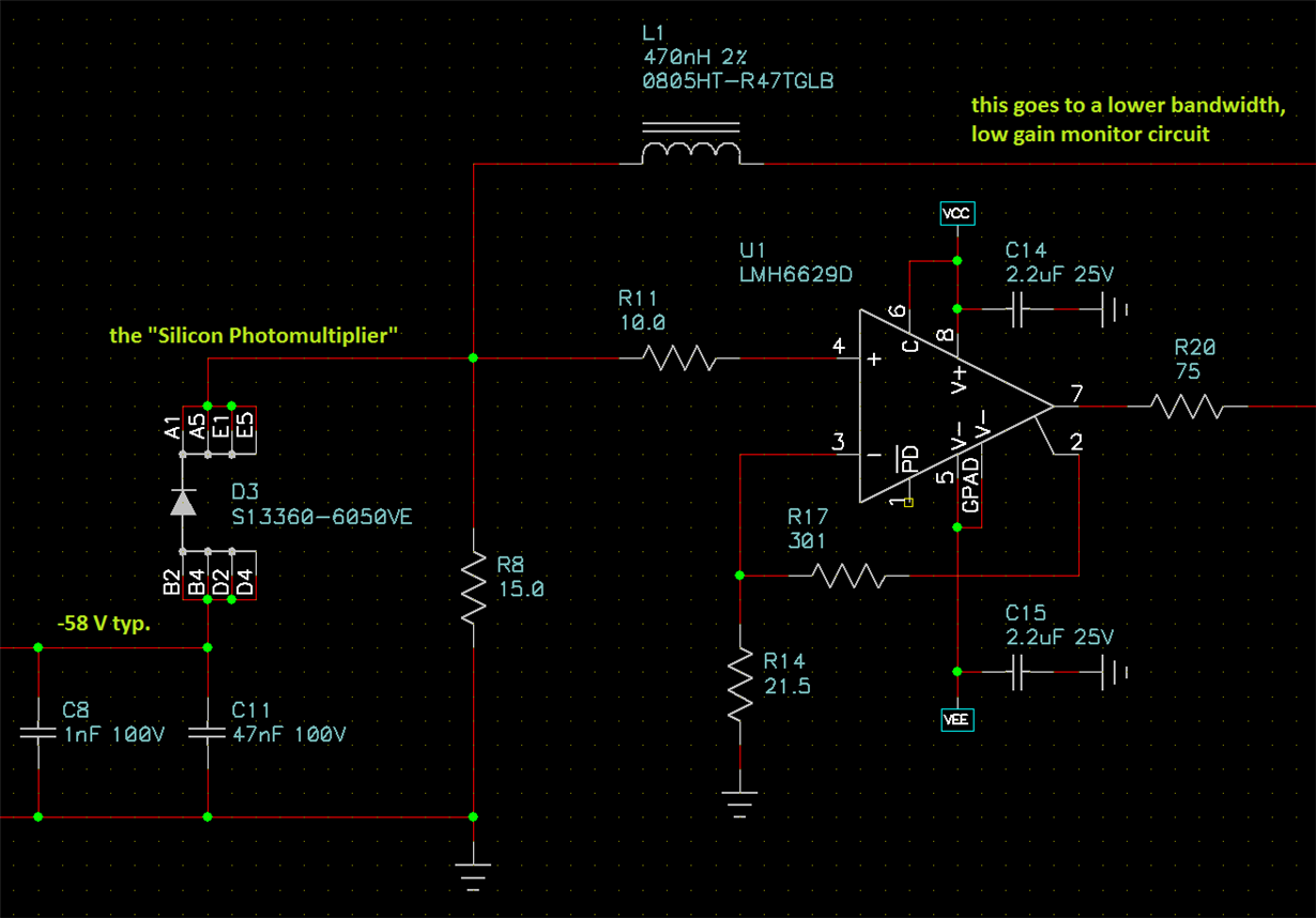
I am designing a circuit using two stages of LMH6629 with +/-2.5V supply to amplify the signal from a "Silicon Photomultiplier" optical sensor. The typical signals of interest will be 1-10 mV, however rare signals up to 7 V will occur (duration a few tens of nanoseconds).

I need to consider if any clamping is needed to protect the amplifier.

The datasheet says absolute max differential input voltage 3 V, but it does not say if there is an internal clamp which protects it (provided I limit the current to +/-10 mA) or not.

The post at ... amplifiers/high_speed_amplifiers/f/10/t/624271  [sorry I do not seem to be able to include a hyperlink] by (TI) says there is an internal clamp, but that was a side remark off the main topic of that thread. I'd like to really check this statement here. Some amplifiers have internal clamp, some do not, some don't need the input-input clamp. It would be helpful if all opamp datasheets would include a bit more of this info. (Why are the simplified schematic diagrams so much out of favor these days?????)

I understand that as far as clamps to the V+ and V- rails, they are there and the inputs can go to ~0.5V beyond either rail or whatever voltage results in at most 10 mA in those clamp diodes.

I look forward to hearing from you; any advice you can give about clamping and protection in the LMH6629 application will be greatly appreciated.

  • I should probably give a schematic here, although it is very straightforward:

    ---

    Also let me add one more question: The circuit could be arranged with either polarity. Is there a "better" / "worse" polarity from the point of view of overload damage, and/or overload recovery time. (I know those are two separate things, I'm just asking if in either perspective there is a difference for different polarity of input overdrive).

    Thanks...

  • Hello Gerard,

    The LMH6629 has clamp diodes that are designed to provide ESD protection. These ESD devices are connected to the power supply rails as well as between the two inputs.

    The ESD devices are not designed for over-voltage protection.  We provide the 10mA guidance to avoid device damage, but the best answer for your question is that if you expect over-voltage events you should provide external protection. 

    So, there are "clamps" in the LMH6629, but they are not really what you're looking for. 

    Does this answer your question? 

    Regards,

    Loren

  • Hello Gerard,

    To answer the second question look at page 6 of the datasheet for the CMVR specification. The amplifier will work with input voltages below the negative supply rail, but only within 1.2V of the positive rail. This means the input will operate closer to the negative supply than the positive.

    Regards,
    Loren
  • hi Loren,

    Thanks for the quick answers. Knowing that there is a bidirectional clamp between the two inputs is good, this means (correct?) that if my external circuit limits the current to 10 mA then there is no risk of damage. What I didn't know before was whether the 3 V absolute maximum was referring to breakdown of, say, the input transistors B-E junctions in which case even a very small current would be damaging. That was my worry; I think you'll agree this is something that designers need to be consider. It's not clearly stated in this datasheet.

    I agree that I'll need to have a series resistor and perhaps external clamp diodes, to limit currents into the input pins.

    About the input common mode range, yes I understand that but I think that isn't really the key property. With the feedback network referenced to midsupply as in my circuit, the amplifier will saturate before we exhaust even the positive-swinging input common mode range. Isn't that so?
    Maybe there is nothing more to be said about recovery time or damage risks for positive vs. negative inputs? If you have any insights about those please let me know; but otherwise I think I can just work with the signal polarity that gives me the simpler overall system.

    Thanks,
    Gerard