This thread has been locked.

If you have a related question, please click the "Ask a related question" button in the top right corner. The newly created question will be automatically linked to this question.

OPA659: Opamp differential high impedance input

Part Number: OPA659

Hi,

I made a differential probe for my scope, but the output signal does not seem nothing I expected, TINA or any similar software simulates.

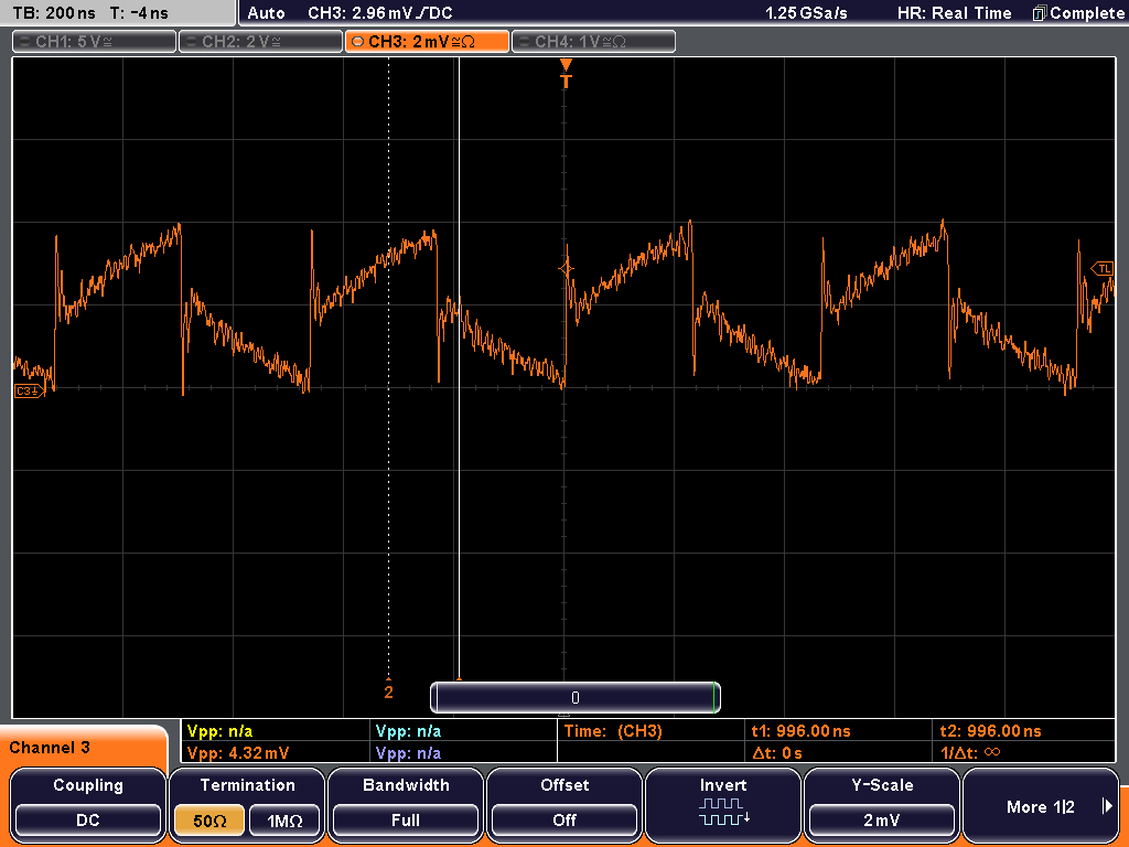
The input signal is 5V, 2MHz square wave, the output should be 5mV (1:1000). I tested the input with DC, and the response was accurate. I suspect it has to do with input impedance, since when I replaced the 1Meg input with 200k and placed 12pF capacitors instead of 3.3p ones the output became what it should be, a nice 5mV square vawe. The input of the opamp is 10^12 and a few pF, I thought it should handle a 1M input. I need high impedance because I intend to use it on 230V line voltage too. As the sharp rising edges suggest the output improves at higher frequencies, but I am clueless why this shape in the few MHz range. Can anyone give me a hint?

  • Hi Akos,

    Looking at the waveform, it looks like the input signal source is not properly terminated. May I know what signal generator are you using for generating the square wave? Does it have 50-ohms output which is connected straight into this differential probe input?

    The other thing to try would be to slow the square wave down to 10kHz or 100Khz and see if the waveform improves. If yes, then it could indicate that the differential probe is bandwidth limited and you might want to think about removing the 3.3pF input capacitors.

    Also, is there a reason as to why you cannot scale down the Rf to 400-ohms while selecting 200k-ohms input impedance? I believe the divide down ratio should still be the same and it should be able to handle the 230V line voltage.

    Best Regards,
    Rohit
  • Hi Rohit,

    There can't be a matching like on 50-50 ohm systems. The purpose of the probe is to be a high impedance (in MOhm range) and the generator is a circuit you are debugging with the scope.

    It seems there is a small parasitic capacitance across the resistors 10-100fF and sharp edges propagate through. If I remove the 3.3p capacitor it gets worse.

    I did have some success by putting 2 x 3 pieces of 1pF across the 1 Meg resistors and 16pFs on the divider side, but I still get some additional high frequency throughput (steeper edges than measured at the generator).

    Divide ratio is 1:1000 with these values, so 1V=1mV my scope is capable to measure with low noise if set 50 Ohm probe input. A 400 ohm resistors would make it 1:5000. I'd prefer higher values, like 10k but then the bandwidth would be reduced accordingly.

  • Hi Akos,

    Understood. It almost looks like the frequency response of the differential probe is peaked up which is leading to sharp edges in the square waveform. Would it be possible for you to increase the size of the inverting input capacitor to 9pF and see if there is any improvement? By increasing the size of the inverting input cap, you are increasing noise gain of the OPA659 at higher frequencies which should take care of this peaking.

    It might also not be a bad idea to measure frequency response on a network analyzer and see if there is peaking.

    Best Regards,
    Rohit
  • Hi Rohit,

    I tried a lot of different capacitors (1.8, 3.3, 5.6, 12, 16, 20pF). As I wrote in my previous post my best result so far was a shunt capacitances of 16pF but I had to place 0.3pF in parallel with the 1Meg too, because without it I got a LP filter. The output became a square wave but it still has an augmented high frequency content (no overshoot, but steeper edges than the input). I feel worried for not having the full understanding of what is going on. The whole thing behaves like a huge band-stop filter with a zero at about 1MHz but no common sense or simulation gives me anything close... I don't have a VNA, I'll check with my spectrum analyzer.