I am designing a Transimpendance Amplifier for a photodiode with OPA847, which has excelent bandwidth and noise performance.
I have found that noise performance is not as expected. Then, I decided to make a minimalist approach: mount just feedback resistor and make noise measurements with it. The result is that noise performance also does not match with my estimations.
In the process I have learned various things:
- The TIA is intended to operate up to 100 MHz. Transimpedance request is 3K5. Paratistics of average quality SMD resistor in 1206 package is not negligible. Finally, I ended using two 1K8 resistors in series. I have stimated (from measurements) its paratistic capacity is about 0.5 pF. Series inductance could be neglected.
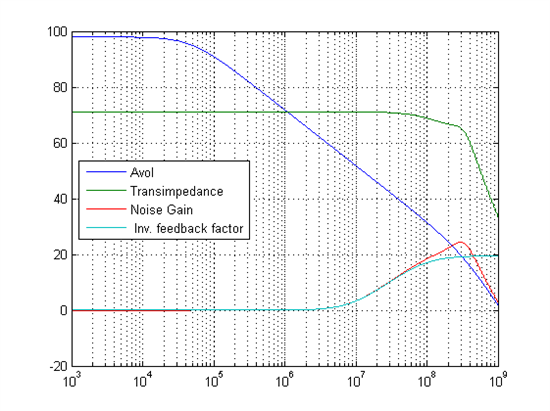
- Single pole models of the operational amplifier open loop gain is not precise enough model and a two pole response is necessary. A second pole at 325 MHz is included in my model.
- Typical noise analysis models (like SBOA066A and many, many others) include simplifications in noise that may pro
Test bench: board under test is done with copper-clad in a dead bug mode, to minimise paratistics to absolute minimum. I have removed copper (in both sides of PCB) under inverting input. From side to side the circuit measures less that 15 mm. Power supply includes ferrite bead and a parallel of 10uF//100 nF. Non inverting input includes 3K9 resistor decoupled with 100 nF. I have also tested with lower values in parallel to be sure if offers low impendance at high frequency but results are the same.
The output of the opamp has a 50 R resistor (1206) direcly connected to SMA female connector. This is connected to male to male SMA adapter and then to a Minicircuits ZFL-500+ amplifier and then to the Spectrum Analizer input. No cables. Having fear of problems of increasing of opamp output resistance at high frequency I also made some tests at 150 R series output resistor, finding very small differences in the noise behaviour (after obvious level corrections).
I am using a laboratory power supply units with linear regulators and 50 cm cables. I have compared results using two power supply units of different manufacturers, obtaining very simmilar results. I also tested with very local supply regulation based on 7805 and 7905 with just the same results.
For feedback resistance I have soldered two 1K8 resistors (1206 package) in series. I have performed tests without feedback capacitors and 0.5 pF ones from Murata. In a previous test I measured transimpedance obtaining expected results (just 1 dB error at 200 MHz maybe due to ouptut series inductance). From them I estimated 0.5 pF stray capacity of feedback resistance.
I have done some measurements, but I will just report the one done with no feedback capacity and my estimations of transfer functions and noises. I have included an stray opamp input capacity of 0.5 pF apart from opamp internal ones, and mentioned stray feedback resistor capacity.
Please, could you give me any clue of what may be failing?
Best regards