Hi,
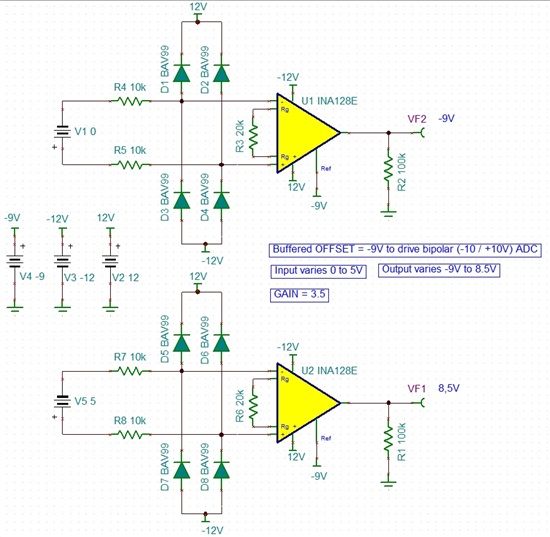
There is a bipolar (-10V/+10V) ADC on my circuit. And want to measure 0V to 5V signal with high empedance circuitry. To not loose ADC resolution I want to add a negative offset in INA128 circuit without using second amplifier. (0V to 5V input; -9V to 8.5V output) Theroticaly and experimentaly (using TINA-TI) applying -9V to INA128 reference input solve my problem. Input and output voltage seems to be within specified limits but what about internal node voltages.
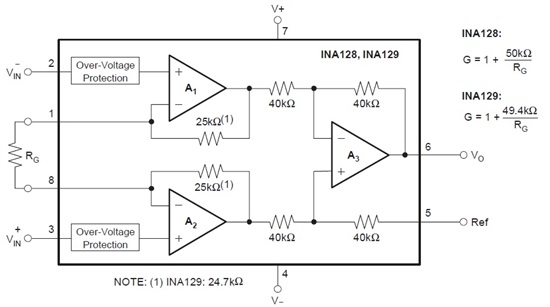
According to my calculation; when input is 5V and output is 8.5V, A2 output node should be 11.25V. But it seems difficult the reach this level with 12V supply. (Is it RRO)
Could you please clearify and make me sure for these ?
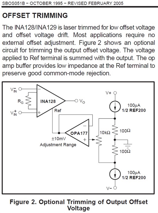
1.) Reference input is just intended for applying small offset nulling voltages or can I use it to apply higher offset ?
2. ) Using -9V offset is adequate for INA128 ? If yes how does it effect the CMRR ?
3.) Using 15V positive supply for INA128 allows me to apply -9V offset to reference pin if 12V supply is not enough?
Best regards.
( Diodes are BAV199 but not found in TINA-TI library so I used BAV99 instead. )