Hi everyone,
I am a physicics trying to design a photodiode amplifier, I have experience in electrical design, but this one is a real challenge for me.
I am designing a photodiode amplifier to measure very low light level at a frequency around 15kHz. My photodiode capacitance is 140pF. The minimum current that I need to detect is around 0.3pA and the maximum is 0.3uA. The scale is very broad so I think I will need different amplification level. This is the first thing that I am not sure about.
1) How to implement different transimpedance amplification level? I though of using ADC161S626 as an interface and a DAC would provide different Vref for the ADC converter. Is this the best way to proceed?
2) The second thing that I have a problem with is the 0.3pA at 15kHz. There is so many choices of op amp that I have become lost. I think the best way to procceed would be to define the maximum amplification I can get at 15kHz considering stray capacitance and then choose an ADC with sufficient bits to get the accuracy I need to get to 0.3pA.
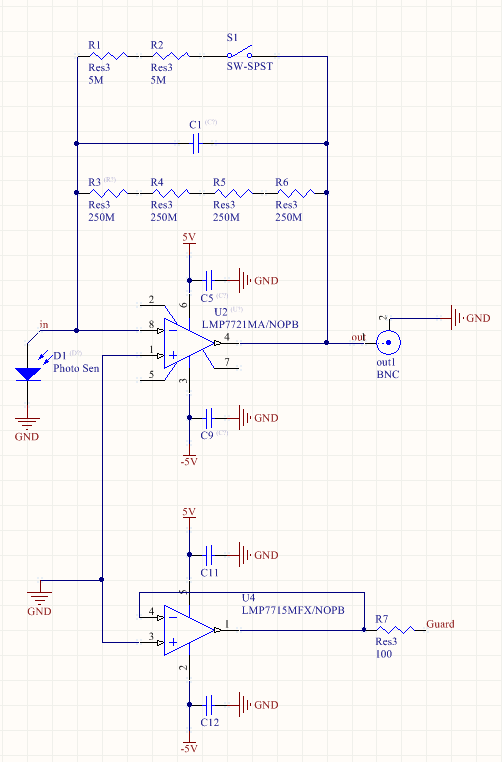
So far, I have looked at the LMP7721, OPA277 and OPA847 with TINA (and a simple photovoltaic circuit) and the maximum I got (while having 15kHz) was a gain of G=5M with a capacitance Cd=1pF. That gives me a minimum of 1.5uV to detect with the ADS1251 (19bits, 20kHz, Vref=0.5V). Is this realistic??
3) Would a phase compensation circuit be usefull in this case? http://www.eetimes.com/electronics-news/4164311/Current-feedback-op-amps-save-power-in-fast-photodiode-applications
Thanks for your help