This thread has been locked.

If you have a related question, please click the "Ask a related question" button in the top right corner. The newly created question will be automatically linked to this question.

OPA227 Open Loop Pole Locations

Other Parts Discussed in Thread: OPA227

What are the locations of the open loop pole frequencies of the OPA227?  I estimate there is a low frequency pole at about 0.08Hz but most op amps have at least one more pole at a frequency higher than the unity gain frequency of the op amp.

I ask because I am designing a low noise composite amplifier with a discrete BJT differential pair front end.  The OPA227 will serve as the second stage amplifier taking the differential output of the first stage from the BJT collectors.  I must know the composite amplifiers open loop response to properly compensate it.  I know the open loop response of the discrete first stage and now only require the open loop response of the OPA227 second stage.

Thanks

--hassan

  • Hassan,

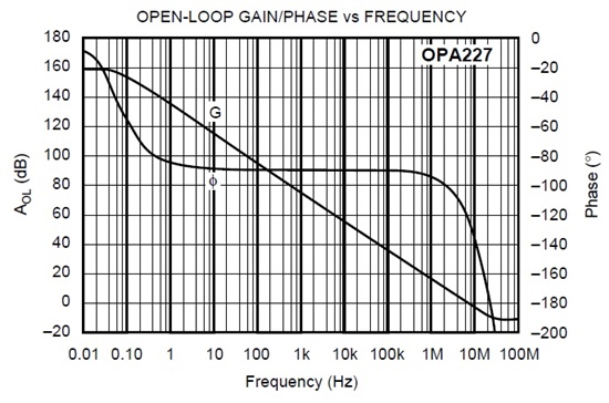
    Since the Gain Bandwidth Product (GBW) of OPA227 is 8 MHz, the dominant pole location, f1, will be a function of DC Open-Loop Gain (AOL) where f1=8.0e6/AOL_DC; thus, for the typical DC AOLof 160dB (1.0e8) the dominant pole would occur at f1=8.0e6/1.0e8=0.08Hz but for the minimum DC AOL of 132dB (4.0e6) it would occur at 8.0e6/4.0e6=2Hz. 

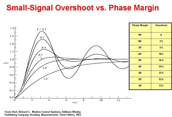
    However, it is the high-frequency pole(s) that determine stability of the overall system as they cause the phase margin to shift from 90 deg to or below zero at the effective bandwidth frequency of the system - see AOL graph below.  In case of OPA227 there also must clearly be a high frequency zero (flattening of AOL curve) followed by at least two high frequency poles but these could be simplified as a single high frequency pole having the same effect on a phase margin - since a single pole causes a phase shift of 45deg at the location of the pole while in the case of OPA227 at unity-gain frequency of 8MHz the phase is shifted by only 30deg (from -90 deg to -120deg), the location of the high frequency pole would have to be around 16MHz.  Of course, as mentioned before, this is over-simplification of the actual system and to analyze stability of the system one also needs to know the open-loop output impedance of OPA227 (not given) at the frequency of its effective bandwidth.  For that reason, the best approach is to apply a small signal (100mVpp square waveform) and to make sure that the output does NOT overshoot by more than 25% assuring at least 40 deg phase margin - see table below.

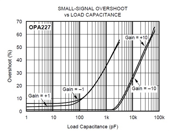
    Short of doing that, the best way to analyze the system is to use the OPA227 macro-model provided on TI website and to simulate various loading effects - I have attached it in this post for your convenience, or to use the Small-Signal Overshoot vs Load Capacitance graph below to assure 40% overshoot or less for any given combination of gain and capacitive load.

    OPA227 Reference design.tsc