This thread has been locked.

If you have a related question, please click the "Ask a related question" button in the top right corner. The newly created question will be automatically linked to this question.

Inquiry regarding voltage output swing on OPA192

Other Parts Discussed in Thread: OPA192

Hello, all

Now we have one inquiry regarding voltage output swing (Vo) on OPA192 from our customer.

Please refer to the item below, and feedback us with your comment.

When referring page 3 of this datasheet, the positive rail of Vo is defined in case RLOAD=10kohm and RLOAD=2kohm individually.

However, they would like to know the case when RLOAD is more than 100kohm.

Please let us clarify how Vo value would be on this case.

We thank you in advance for your information.

Best regards,

  • Atsushi,

    In addition to 2k and 10k load, the output voltage swing of OPA192 is also specified for NO LOAD (10mV from rail) that would be virtually the same as the swing with 100k load or greater-see below.

    However, the voltage output swing shown in the table above is based on the Ron resistance of the output transistors under fully trioded conditions - a non-linear operation which will result in a very significant output voltage error.

    Therefore, if your application requires any precision in the output voltage, you must adhere to the output voltage range specified in the condition column of the AOL test - 300mV from either rail (see below).


  • Hello, thank you for your prompt reply.

    Our customer would like to know the estimated voltage output swing in case of following condition. (on their case, slight influence is important to select which parts are suit for their sensor application.) 

    V+=+12V, V-=0V, +IN=0V, -IN=0V and RLOAD=100kohm

    Also, they would like to know the difference in case of TA=+25℃ and TA=-40~+85℃ individually.

    We thank you once again for your information.

    Best regards,

  • Atsushi,

    What you describe is a non-linear operation where the output is driven to a negative rail.  As I said in my previous post, the non-linear output voltage swing of OPA192 is specified for NO LOAD that would be virtually the same as the swing with 100k load; therefore, according to the datasheet, with 100k load the output should swing within 10mV of either rail at 25C.  This specified output voltage swing should not vary more than +/-50% over the entire specified temperature range from -40C to 125C -  5mV to 15mV from negative rail with Rload connected between the Vout and GND.  However, the output voltage swing is only tested at 25C and the over temp variation is just my estimate.

  • Hello, thank you for your continuous support.

    With regard to your previous comment that " the output voltage swing of OPA192 is also specified for NO LOAD (10mV from rail) that would be virtually the same as the swing with 100k load or greater", 

    Please let us clarify whether this device has already been entered into saturated area when the load is 100kohm.

    We thank you once again for your information.

  • Atsushi,

    The OPA192 output stage linear operation is specified in the condition column of the AOL tests: 300mV from either rail with 10k load and 600mV from rail with 2k load. 

    When you drive the output to a negative rail (0V), it will ALWAYS operate in the non-linear region and the only question becomes how close to the rail it can get (this depends on the load) - with 100k load the output should get within 10mV. 

    If it is critical for the output to swing all the way to negative rail, in order to accomplish this you may use a pull-down resistor, Rpd, connected to an auxiliary negative supply, Vee.  In such case, appropriately sized pull-down resistor must be chosen in conjunction with the choice of negative supply to assure around 0.5mA to 1mA being sunk from the output stage - entire current from the output stage must be diverted thru Rpd so there is no current left in the lower output stage transistor;  for example, try to use Rpd=10k with Vee=-5V and if this does not bring output to 0V replace Rpd with lower value resistor (thus increase sinking current).

  • Hello, thank you for your continuous support.

    With regard to Vo rail, please let us clarify about the interpolation between RLOAD=2kohm and RLOAD=10kohm.

    We would appreciate if you could disclose the graph which describes the Vo transient between these conditions.

    We thank you once again for your information.

    Best regards 

  • Atushi,

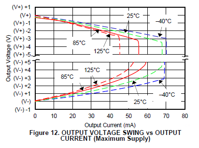
    What is important in determining the op amp output voltage swing to the rail is the output load current. Since our datasheet specifies 2k and 10k load connected to mid-suppy (ground) with +/18V supply voltage, this means that the actual load current is about 9mA and 1.8mA, respectively.

    The graph below shows the Output Voltage Swing as a function of Output Current.


  • Hi,

    There is a similar problem, please let me join this site on the way.

    Fig.12 above shows "Output Current vs output Voltage (to Rail)" when using ±18V power-supply
    Is there a characteristic graph in the same way when using ±2.25V ?

    In the absence of this graph, at the time of ±2.25V power-supply,
    when 5mA and 8mA is sourced(opamp output current),
    How many Voltage is the Output Voltage from the Rail?

    best regards