This thread has been locked.

If you have a related question, please click the "Ask a related question" button in the top right corner. The newly created question will be automatically linked to this question.

noise on the vdd when connecting the load to the lmv881

Other Parts Discussed in Thread: LMV881

Hi

I am using lmv881 in order to generate a 10 Hz 2.5V sin wave - (2.5*abs(sin(2*pi*10*t))) 

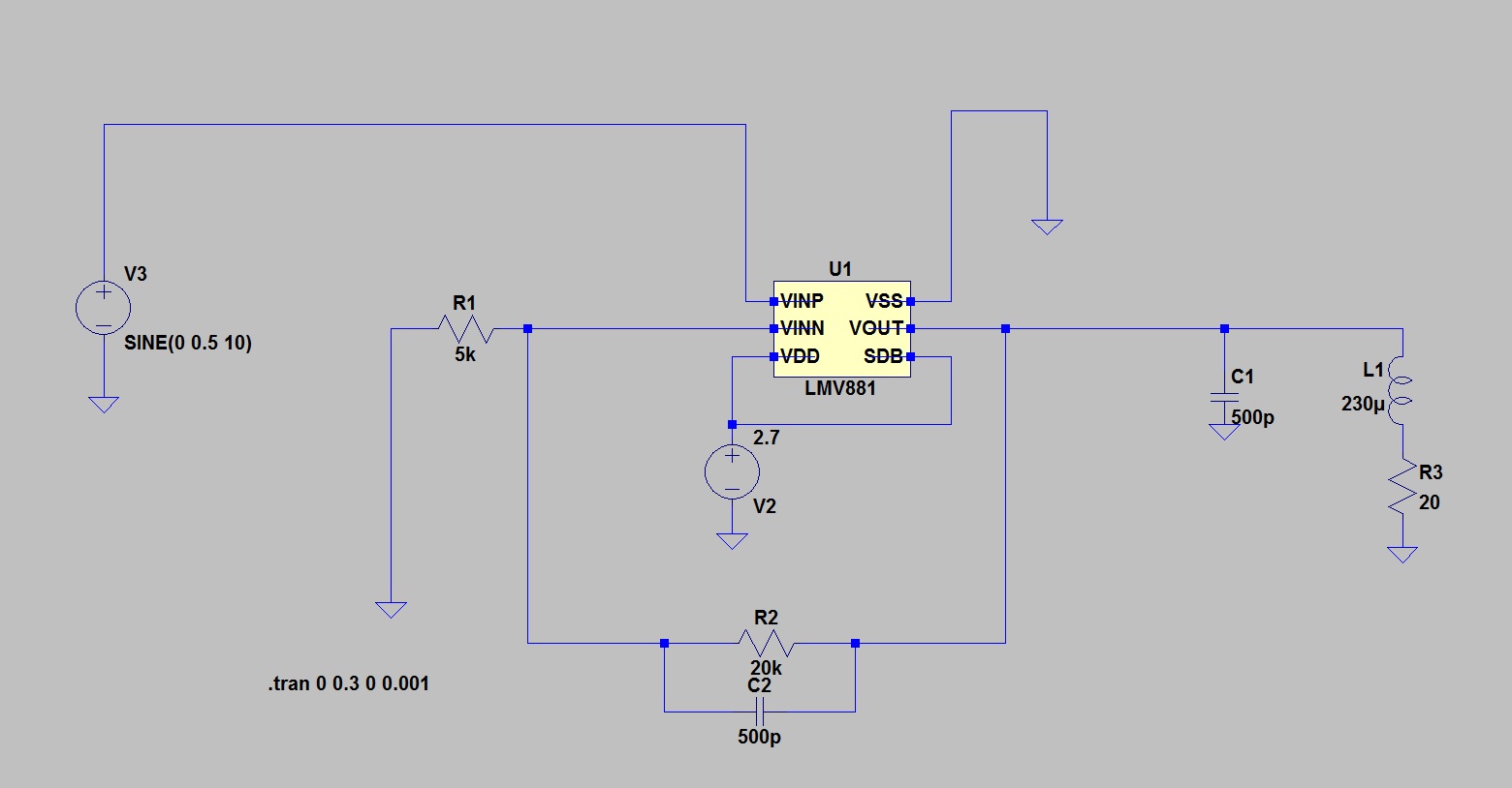
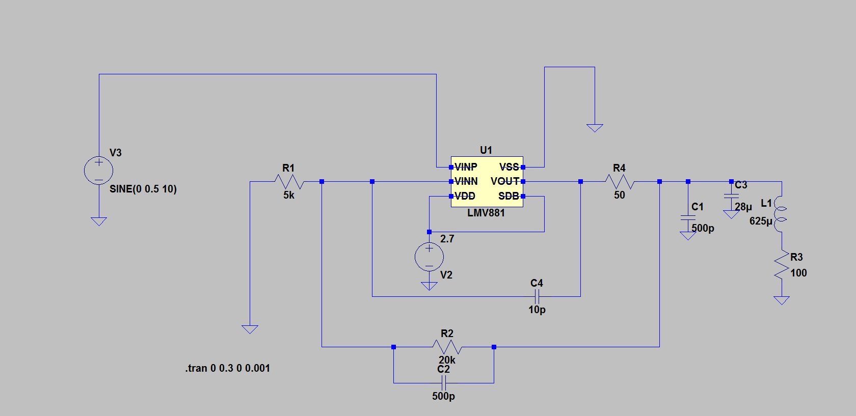
I connected the the amp according to the picture below (20ohm + 230uH is my load).

from my simulation  I have seen that this should be working

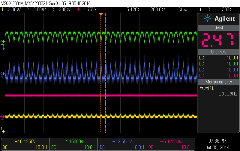
when I connect it to my circuit it worked without the load but when connecting the load the Vdd starts to noise and jump in the same freq the sin wave (10 Hz) this influence my whole circuit and this 10 Hz noise reflected on any signal in the circuit .

why is that happening? and how can I fix it? 

  • Hi Sam,

    The "noise" you see is probably an oscillation.

    The LMV881 is not designed to a 500pF load directly. There is an entire section in the datasheet Apps Section explaining this (pg 14).

    You need to add a 50 ohm resistor in series with the output to isolate the capacitance. This resistor can be placed within the feedback loop to maintain amplitude accuracy (a few pF may be needed to be added between VOUT and VNIN).

    Regards,

  • Hi Paul

    thanks for your answer.

    is this what you meant?

    I tried this but it didnt change my signal.

    (please also see I added the tacitness of the coil which I didnt added before...)

    the issue is that wen I connect it to a power source it dosent reflect the oscilation on the Vdd it happenmds only when I do it with an LDO that is connected to my circuit.

    what do you think? maybe I dont have enough current? from the LDO?

    or you still think it is relatd to isolation?

    thanks in advanced,

  • HI Sam,

    Yes. Correct. If the output still oscillates, you may need to add a ~10-20pF cap between VNIN and VOUT (feed-forward cap) to maintain stability.

    What is the frequency of the VDD oscillation? MHz? 100's of KHz? Hz?

    LDO's generally require bypass capacitors with a certain capacitance value and ESR range for both the input and output capacitors. Read the datasheet for the LDO carefully to see if it mentions the minimum ESR values and recommended capacitor types. There may also be a graphs showing this. The caps generally need to be ceramic or tantalum - not "trash can" electrolytics.

    Regards,

  • Paul Hi

    thanks for your swipe answer.

    did you mean to connect it that way (see below)?

    I connected it that way with 10-20 pF cap and haven't saw any change on my circuit.

    the freq I am activating the amp is 10Hz and those are the oscillations I see in the in my circuit.

    the Ldo have good caps according to it data sheet and I dont see the oscillations on it output.

    the issue is that when I connect the amp (it Vdd) directly to a battery instead of to the Ldo output the oscillations in the circuit stops so I think it is going back through the LDO  and to the circuit but the out put line is steady even when the Ldo is connected to the amp.   

    what do you think?

    Thanks again,

  • Hi Sam,

    The circuit you show above will draw about 17mA from the supply on the peaks. It sounds like your regulator cannot supply the current.

    What regulator are you using?

    Can you provide a more detailed schematic?

    Can you provide a scope photo - showing the input, output and supply voltages?

    Regards,

  • Hi Paul

    1.The regulator I I use is lt3061: http://www.linear.com/product/LT3061#overview.

    2.regarding the schematics I still dont have but I am connecting the LDO to rectifier that give it between 3 to 5V.

    the Ldo gives a controller and the amp 2.5V. the controller generate the sin wave and also connected to the amp.

    I will send drawing when I will have now I am just in prototyping satage and testing the amp.

    the amp itself is connected as shown in the last post the "vinp" is connected to the DAC of the controller and the sdb and vdd is connected to the LDO. 

    3. attached is my scop screen shut.

    1 is the voltage after the rectifier.

    2 is the voltage on the coil.

    3 is a signal in the circuit.

    4 is the voltage in the LDO output.

    the thing is that the voltage the is drown from the LDO is only 37mA and when I raise the voltage the the current is not rising so it is not the current and the LDO can flow 100mA.

    when I change the amp to drv 8601 this problem is solved so I believe the oscillations comes from the amp.

    when I connect the Vimp to a constant voltage the oscillations stops.

    when I connect the Vdd to battery the oscillations also stops.

    what do you think?

    thanks in advanced.

  • Hi Sam,

    What is driving the input (VINP)? Is it floating?? You cannot let the input float.

    Regards

  • Hi Paul

    As I wrote the "vinp" is connected to the DAC of the controller. the DAC is generating the sin(2*pi*10*t) that feeds the in+ of the amp.

    is it make sens to you or that something is missing?

    one more thing, the LDO if feed from rectifier. maybe I need insulated LDO?

    or something like this?

    Regards,


  • Hi Paul 

    have you seen my last answer?

    Regards