This thread has been locked.

If you have a related question, please click the "Ask a related question" button in the top right corner. The newly created question will be automatically linked to this question.

OPA549: PSpicesimulation problem

Part Number: OPA549

I am having trouble with the OPA549 model.

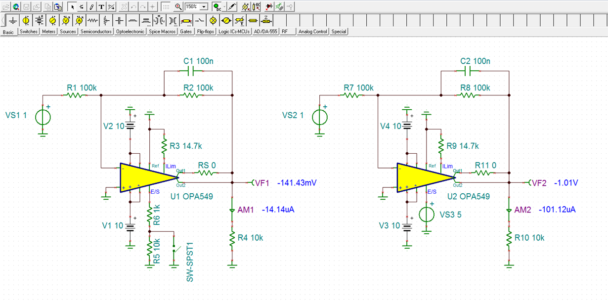
Here is the test circuit I amusing.  The inverting pin is connected to a 1Vdc source through a 100 kOhm resistor.The output should be -1V.

It ix -141..114629393mV to -141.462593mV.  984.8pV pk-pk triangular ripple

with a period of 38.288uS.

Is there a problem with the model or my test circuit?

This circuit is used in a larger system and this schematic represents

How it is used in the system except for the 1V source input and the 10K load.

Inverting terminal Input resistance is 100 kOhms.  Feedback is 100 kOhms shunted by a 0.1uF capacitor

Ref is grounded.

Ilim is connected to ground through a 17.4 kOhm resistor shunted by a 0.01uF capacitor.

E/S is connected to ground through a 1 kOhm and 10 kOhm resistors to ground.  There is a voltage controlled switch connected at the junction of the 1 kOhm and the10  kOhm resistors

The 1 kOhm is tied to the E/S pin and the 10 kOhm is grounded.

non-inverting pin is grounded.

Vcc aand Vee are connected to +10V and-10V respectively


  • Hello Clyde,

    I tried to reconstruct your OPA549 circuit based on the description you provided. If you connected the OPA549 model's E/S pin as I show on the lefthand image shown below, the op amp would be placed in shutdown mode. Anything appearing at the output of OPA549 would be a related to the resistive divider formed by the input, feedback and load resistors and any shutdown mode currents the model exhibits. However, if the E/S pin is biased as shown on the righthand side below, with a positive supply level set in relation to VREF, the op amp is placed in enabled mode. The op amp is then operational and the expected -1 V appears at the output.

    Do note that the 100 nF capacitor across the 100 k feedback resistor rolls the amplifier off at at a very low frequency. The -3 dB bandwidth is about 16 Hz. If that is what you need, okay.

    Regards, Thomas

    Precision Amplifiers Applications Engineering

    OPA549_model_test_01.TSC