This thread has been locked.

If you have a related question, please click the "Ask a related question" button in the top right corner. The newly created question will be automatically linked to this question.

OPA350: DFMEA for OPA350

Part Number: OPA350

Hello,

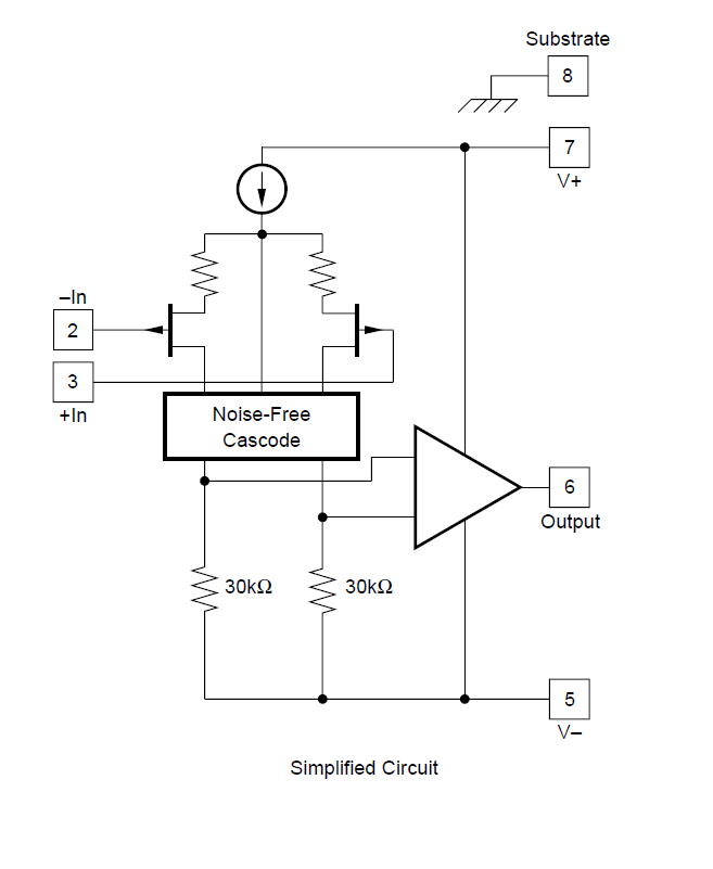
For DFMEA failure analysis, looking at the OPA350 op amp internal diagram below:

It seems the input voltage on the op amps + and – terminals will not likely get to the output of the op amp in case the op amps fail.
In case the op amp fails, it looks like only power supply rail voltage may propagate to the output? Is this understanding correct?

Thank you, Keith

  • The simplified diagram you attached shows JFET instead of CMOS input differential pair and thus it does not correctly represent circuit topology used in OPA350.

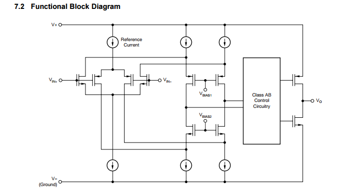
    Below please see simplified schematic of OPA350.

    Having said that, I am not sure what you exactly mean by saying "It seems the input voltage on the op amps + and – terminals will not likely get to the output of the op amp in case the op amps fail. In case the op amp fails, it looks like only power supply rail voltage may propagate to the output. "

    Since the op amp is typically used in close-loop configuration, the voltage at the input terminals and the external components used to gain up the signal directly control the output.  A failure of the op amp does NOT necessarily mean that the signal path between the input and output had been severed, and thus depending on the type of internal damage and configuration used, the output may respond differently.  Having said that, because of the very high open-loop gain, AOL, in most such cases the output will end up at one of the rails.  This, however, does not mean that “only power supply propagate to the output” but rather that the damage related erroneous differential voltage between the input terminals gets gained-up by open-loop gain of the op amp resulting in output being pushed against one of the rails.