This thread has been locked.

If you have a related question, please click the "Ask a related question" button in the top right corner. The newly created question will be automatically linked to this question.

Vos Measurement

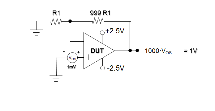
I am reading a slide document talking about op amp specifications. When it comes to the issue of Vos measurement, a circuit as follow are exhibited. And it was noted that -

"If I was ask to come up with a test circuit for Vos, I would have came up with something like this. When you realize that Vos varies depending on the output, it becomes clear that this circuit is not a good test method."

And it was stated that there are two disadvantages -

"- The finite gain has an effect

- The output isn’t at zero volts (open loop gain error)"

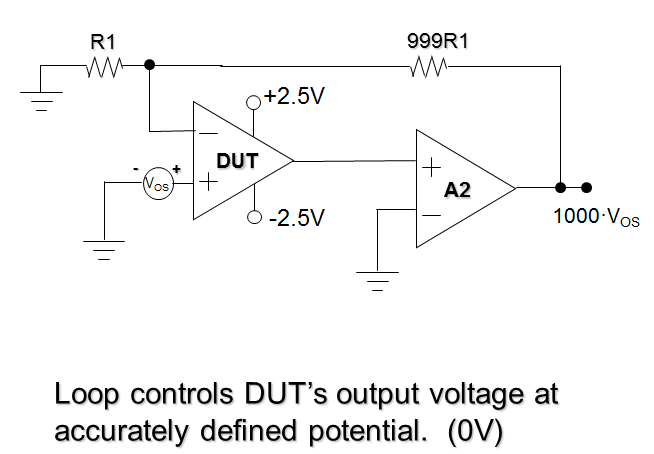
and then, a circuit was provided as follow.

So I just want to ask:

1.How to comprehend that "Vos varies depending on the output "?

2.What will happen if the output isn't at 0 volts for the Vos measurement. Does it has a considerable influence?

3.How the second circuit solve this problem?

  • Hi Robin,

    Please send the document you are referring to here.

    Thanks,

    ~Leonard

  • Op Amp Specifications.pptx

    Hi Leonard,

    I'm an analog FAE NCG (FSO rotation) located in Shenzhen OEM Team, China, and I'm reading the Op Amp Specifications authored by Keith Kendall & Bruce Trump.

    And I am looking for the  answer to the question about how to measure Vos precisely

    Thanks,

    Robin Liu,

    Shenzhen, China, Analog FAE

  • Hello Robin,

    1.)  The open-loop gain specification is defined as the change in input offset voltage vs. change in output voltage (Aol = Delta_Vos / Delta_Vout).  Therefore as the output voltage changes, so does Vos.

    2.)  This depends on the Aol and Vos levels of the op amp.  If you're looking for a coarse measurement then it is probably fine.  If you need a precision measurement then it's probably not okay.

    3.) In circuit 2 the IN- pin of the A2 servo amp is connected to GND.  Therefore A2 will control it's output voltage such that the IN+ terminal is also GND to achieve the "virtual short".  Since the output of A1 is connected to the IN- pin of A2, the output of A1 will be GND regardless of Vos. 

  • Robin,

    Additionally, you may find the following article useful for understanding why the offset changes with the output: 

    Regards,

    Zak Kaye

  • Thank you!

    robin Liu
  • Thank you!

    ~Robin Liu
  • Excuse me, for this issue, I am still confused about the relationship between offset voltage and output voltage, as well as the definition of Aol. Let’s look at the simulation test.(I assume TINA can well manifest the spec)

    First, measure Vos using the one-op amp circuit as figure 1. We can see the output voltage is -394.89mV. And we think 1000 • Vos = -394.89mV, so Vos= -394.89uV.

      Figure 1 one-op amp circuit

    Second, measure Vos using the two-op amp circuit as figure2. We can see the output voltage is -402.35mV. And we think 1000 • Vos = -402.35mV, so Vos = -402.35uV.

     Figure 2 two-op amp circuit 

    Now, we can see the gap between the value of Vos measured with different circuits, “nearly so, but not quite ”. According to the article “Offset Voltage and Open-Loop Gain—they’re cousins” ,and I believe you mean Aol = Delta_Vout/ Delta_Vos , this is the definition of the Aol spec, we think the test value 402.35uV is relative well, while the value -394.89uV, is not good, for the output is not 0 volts, but -394.89mV. In order to calculate easier, let’s assume Aol is equal to 120dB(10^6). Then output voltage of -394.89mV will only causes -394.89nV change to Vos.

    Question: So now that the Delta_Vout of -394.89mV will only cause -394.89nV Delta_Vos, how to explain the gap from -402.35uV to -394.89uV?

          _____________________________________________________________________________________________________     

    In fact, the gap is depending on the change of deferential input of op amps . It is equal to output voltage divided by closed loop gain (Vout/Acl). (So the deference here is Delta_Vout/Aol or Delta_Vout/Acl).

    The follow is a hypothetical analysis from me.

    Here the Vos is modeled as a DC voltage source serial connected to the noninverting input, and Aol is the finite open loop gain of an inner amplifier, as show in figure 3.


    Figure 3

    Vout = ( VIN- — VIN+ — Vos ) • Aol                              (1)

    Vout = ( VIN- —VIN+) • Acl                                             (2)

    So,

    ∆Vout = ∆ ( VIN- — VIN+)• Aol  — ∆Vos  • Aol           (3)

    ∆Vout = ∆( VIN- — VIN+) • Acl                                       (4)

    ∆ ( VIN- — VIN+)• Aol  — ∆Vos  • Aol = ∆( VIN- — VIN+) • Acl

    So,

    ∆Vos  = ∆ ( VIN- — VIN+) ( Aol  — Acl ) / Aol

      ≈ ∆ ( VIN- — VIN+)                                                  (5)

    So,

    ∆Vout  ∆Vos • Acl                                                              (6)

    Confusion: I think formula (5) and (6) explain the result of the simulation test. But I don't know whether I can comprehend this issue as this. However, in this condition, the spec Aol will not be Vout / ∆Vos.


    Thanks,

    Robin Liu,

    Shenzhen, China, Analog FAE


  • Robin,

    I think you have misunderstood the functioning of the op amp in closed loop in your hypothetical derivation. If you look back at the datasheet however you will find that the fact that the output is sitting at -394uV can be entirely accounted for by the open loop gain error mentioned above. From the datasheet, the DC open loop gain is 50V/mV. This means with the output at 394mV there will be an additional 7.88uV of offset at the input of the amplifier. This is almost exactly the difference you are seeing in your two measurements.

    Regards,

    Zak Kaye