This thread has been locked.

If you have a related question, please click the "Ask a related question" button in the top right corner. The newly created question will be automatically linked to this question.

TLV274-Q1: TLV274-Q1 How to measure Input Offset Voltage

Part Number: TLV274-Q1
Other Parts Discussed in Thread: TLV274

Hello

I want to measure the Input Offset Voltage of the TLV274-Q1.
We constructed the circuit as below to measure Input Offset Voltage.
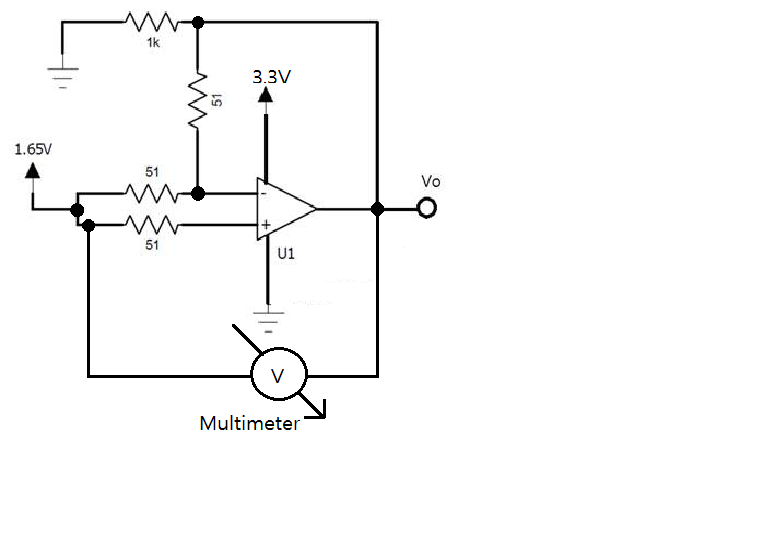

However, the measured value exceeds the guaranteed range of this product.(7mV max)
The measurement result is about 8 to 9 mV.
Therefore, I would like to inquire whether the measurement method we used is correct.

Please let us know if there is a way we can measure more accurately.

  • Yoo,

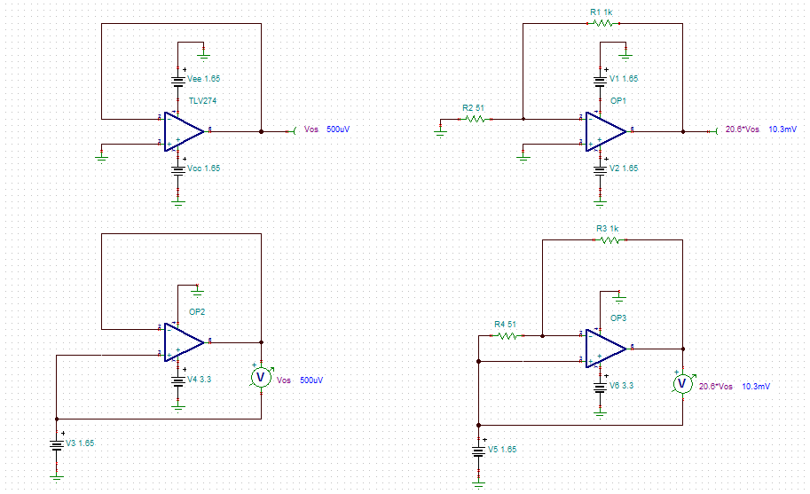
    Your TLV274 Vos measurement setup is incorrect since it is referenced to ground instead of mid-supply. Below please find the correct configurations for a single and dual supply Vos measurement in gain of G=1 and G=(1+1k/51)=20.6

    Since TLV274 is CMOS input amplifier with dual polarity input bias current, there is no need for resistor in series with positive input terminal.  I have also attached the schematic for your own simulations.

    TLV274 Vos.TSC

  • Hello Yoo,

    Here are my suggestions:

    1) Accurately measure each resistor independent of the circuit and calculate the transfer function gains accordingly. Note that there is both inverting and non-inverting gain in this circuit.
    2) Accurately measure the input voltage.
    3) Now that you have accurately measured the input and gains, calculated the 'ideal' output voltage and compare it with the measured result.

    It should be noted that we don't typically use this circuit to measure offset voltage. We typically place the device in a higher gain than 1V/V.

    Here is a good forum link that you may find interesting:

    e2e.ti.com/.../388983

    Perhaps the easiest way to measure Vos is to use a dual supply, place the circuit in a large gain, ground the inputs, and then measure the output. That way you only have 2 resistors to measure an no input voltage...in your case you have to accurately measure 4 resistors and the input voltage. One last note...the data sheet does specify a source resistance of 50ohms (probably best to use a 49.9ohm resistor) and load resistance of 10kohms connected to mid-supply (ground if you use a dual supply).

    Hope this helps!
  • Hello Yoo,
    I presume that our recommendations helped you come to a conclusion. If not, please let us know how we can help further. If we don't hear back from you by tomorrow I will close this thread. You can always open it back up by replying.
  • Dear Mr.Semig


    Thank you very much for your support!!


    I am testing it in the way you have advised.

    But now I have one question. If a Vin offset voltage is generated, does it affect only the Vin "offset x Gain"?

    Or can it affect the Gain itself??

    Or are there other side effects that can affect Vout?

    Pleas give me your advise!!


    Thank Yoo!
  • Hello Yoo,

    There are multiple sources of error besides initial input offset voltage.  These include, but are not limited to, CMRR, PSRR, drift, shift, noise, and the error associated with the drift/shift of the device.

    I highly recommend reviewing all of the videos we have online at http://www.ti.com/precisionlabs

    Thanks!