This thread has been locked.

If you have a related question, please click the "Ask a related question" button in the top right corner. The newly created question will be automatically linked to this question.

OPA860: OPA860 sample& hold circuit

Part Number: OPA860
Other Parts Discussed in Thread: OPA615, DEM-OTA-SO-1A

Hi,

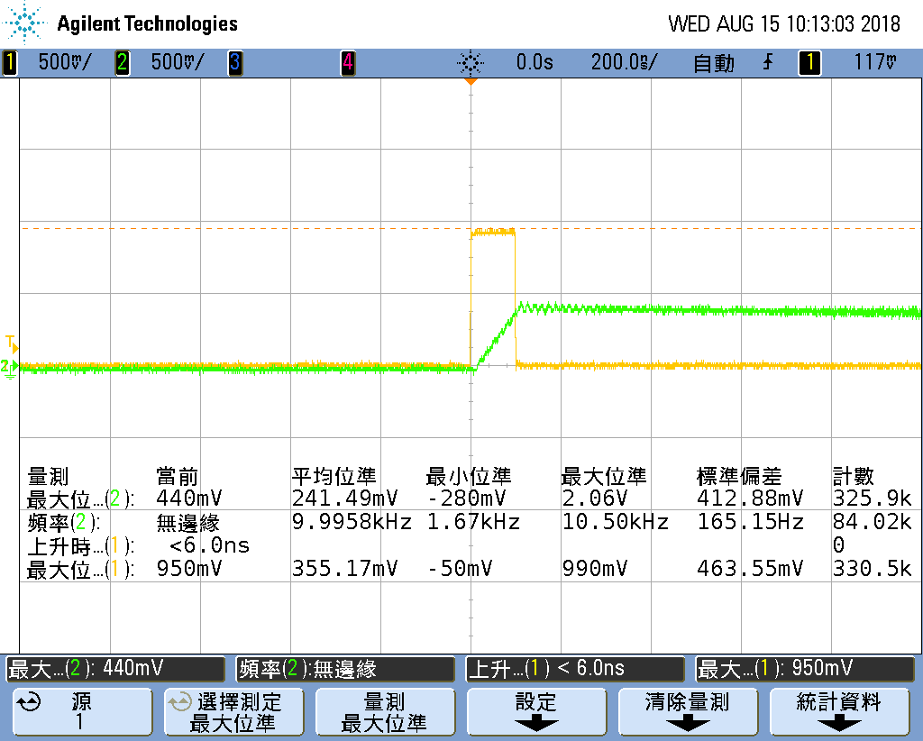
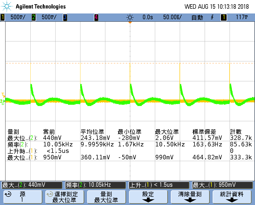
Attached is the sample&hold circuit with OPA860, but  the result  is not correct with TINA simulation, please give me some advice. Thank you very much.

OPA860 (2).TSC

Best regards

kailyn

  • Hi Kailyn,

    do you mean this?

    Or do you mean the sample and hold circuit shown in figure 45 of datasheet of OPA615?

    Kai

  • Hi Kai,
    Thankyou for your reply, and how to selec the value of R7 and R8?
  • Hi Kailyn,

    the circuit is actually an integrator and should be seen in a larger context:

    www.ti.com/lit/an/sboa047/sboa047.pdf

    Figure 27 of this link shows how this integrator has to be combined with a sample/hold scheme:

    What is not mentioned in all these documents is that the integrator output shows a bouncing and needs some 10µs to relax. This can be seen in the simulation when the time axis is expanded to 100µs:

    Now R7 comes into play. If it is chosen too high, then the relaxing time increases. And if it is too low, then the bouncing gets some ripple:

    R8, on the other hand, determines the signal current which is mirrored out of the "collector" output of diamond transistor and by this sets the change rate of the voltage of integrating capacitance C5:

    Kai

  • Hi Kai,

    How to increase the hold time?
    thanks.

    Ric
  • Hi Ric,

    double C5, double R7 and halve R8. But keep an eye on the output offset voltage, which increases when you increase C5.

    kailyn1.TSC

    Kai

  • Hi Kai,

    I made a PCB with OPA860 to implement sample & hold.

    I followed your schematic, below is the experiment result.

    Input: 950mV, 100ns of pulse.

    The output voltage dropped to 450mv, the gap is too large, and I want to hold the pulse to 10us.

    In my experiment, the value of C5 is 68pF, R7 is 820 ohm, and R8 is 560 ohm.

    Is there any reference design of OPA860 sample&hold circuit from TI?

    Please advise how to implement it.

    Tahnks.

    Ric

  • Hi Ric,

    can you show us a full schematic of your circuit?

    Have you read this link?

    www.ti.com/lit/an/sboa047/sboa047.pdf

    How have you set IQADJ?

    Some words about this circuit. The advantage of this OPA860 and the diamond structure is its extreme speed. In the 90ies I have built a peak detector with the OPA660 which was able to detect pulses of only 1ns duration. But precsion is not its strength. If you have pulses of 100ns and desire hold times of 10µs you probably should look for another circuit.

    Kai
  • Hi Kai,

    I attached the schematic as below.

    I use the PCB of DEM-OTA-SO-1A Demonstration Fixture.

    The IQADJ set 220 ohm.

    I need to hold a 1V, 5ns~10ns of pulse to 5us~10us.

    Can you please advise us how to implement the function with OPA860?

    Thank you.

    Ric

  • Hi Ric,

    if you have pulses of different length, an integrator might not be a good solution, because the output voltage of an integrator is proportional to the area under the pulse. Using a peak detector might be a better idea. I would try this scheme:

    These are two peak detectors in a row, the first for a fast rise time and the second for a slow decay time.

    In the following the response of a 5ns pulse is shown:

    Here the response of a 10ns pulse is shown:

    Of course, this is no ready circuit but only an idea. Play with it ...

    In any case you must take very good Schottky diodes with very low junction capacitance and very fast switching times. I usually take the HSMS-2812 for such circuits.

    kailyn3.TSC

    Kai