This thread has been locked.

If you have a related question, please click the "Ask a related question" button in the top right corner. The newly created question will be automatically linked to this question.

TPL5010: What is the minimum rising slope of VDD that will lead to power on reset

Part Number: TPL5010

Hi,

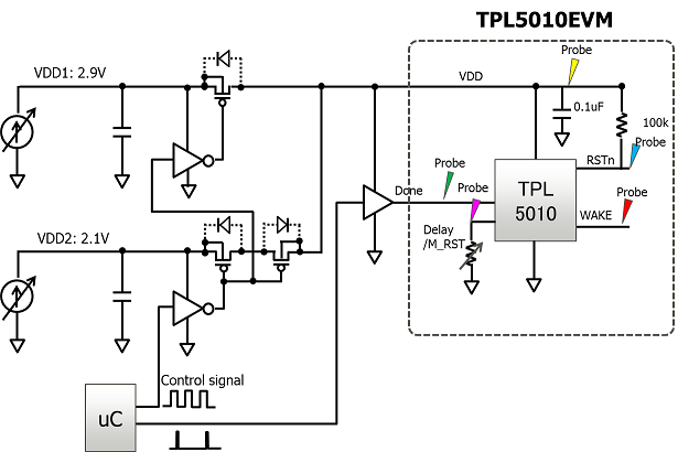
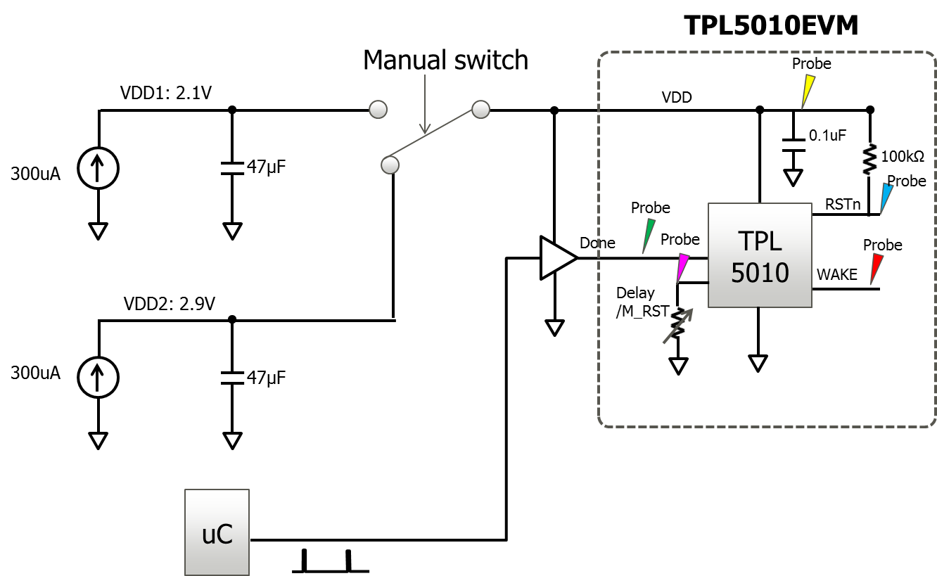
I observed a power on reset phenomenon in TPL5010 when its supply voltage VDD rises up from 2.1V to 2.9V in 1.45us.

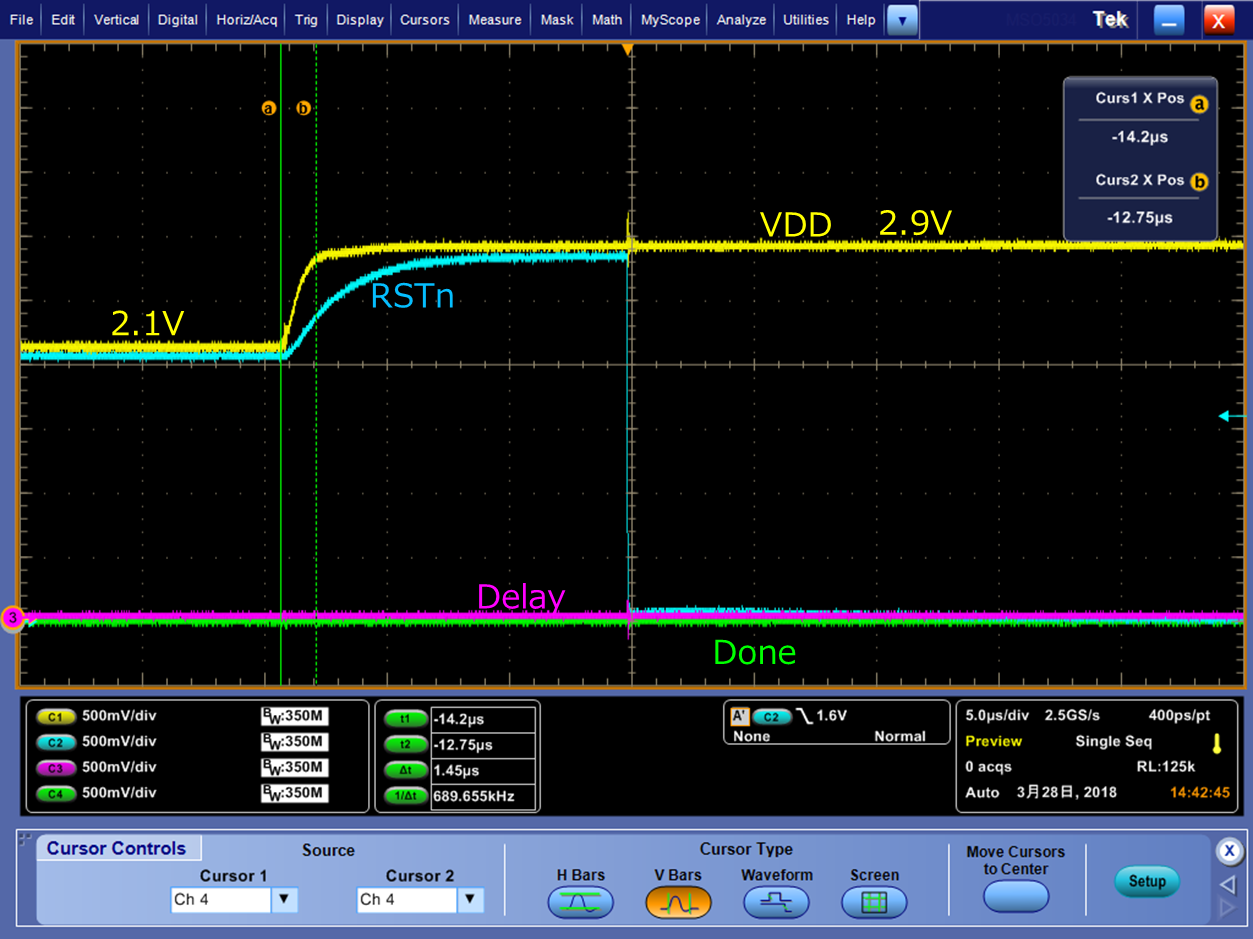
The test result is attached. The yellow line is VDD; the light blue line is RSTn; the pink line is Delay signal and the green line is DONE signal.

After a steep increase in VDD, the RSTn signal falls down to 0V and the timer is reset.

Can you tell me what conditions will cause the power on reset phenomenon in TPL5010?

 For example, is there a minimum rising slope of VDD that will lead to the power on reset?

(the rising slope of VDD=ΔV/Δt, where the ΔV represents the increased value of VDD,  Δt represents the time that it takes for VDD to rise up.)

I think it may be quicker to draw the conclusion by running a simulation.

I am wondering how the circuit works when the VDD rises up. It will be very helpful if you could provide me with a detailed block diagram of TPL5010.

I asked the same question 9 days ago. But it is still not answered.

I would appreciate if you could answer my question quickly.


Sincerely,

Hong

  • Hi Hong,

    I set this up on my bench to duplicate. I am able to rise VDD from 2.1V to 2.9V in 200us and I do not see a power-on reset. The programmable power supply that I have cannot rise any faster; I am looking into an alternative method to determine the minimum rising slope.

    Kind regards,
    Lane
  • Dear Lane,

    Thank you for your reply.

    My test bench is attached.

    I used two current sources to supply 300uA to two 47uF capacitors and limited the voltages of current sources to be 2.1V and 2.9V seperately.

    So the two 47uF can be regarded as two stable voltage sources of 2.1V and 2.9V seperately.

    Then I switched the supply voltage of TPL5010EVM from 2.1V to 2.9V by using a control signal generated by the MCU.

    This is the way I observed the power on reset phenomenon of TPL5010.

    We are considering to use to TPL5010 in our next product.

    We have made the production prototype and troubled with the power on reset (PoR) phenomenon.

    As it is very close to the dealine of production design, I want to know urgently the conditions that may cause the PoR.

    Can you confirm the PoR by simulation? I think it takes much less time to simulate it than to test it.

    I would be very happy if you could respond to me as soon as possible.

    Kind regards,

    Hong

  • Dear Lane,

    I am sorry to bother you again. But I am really in urgent need to clarify the conditions that may cause PoR phenomenon.

    We are preparing a press release for the new product using TPL5010.

    If the PoR phenmenon is not clear, the release date for the new product will be postponed.

    So I really want to know the results immediately.

    Can you run a simulation and draw the conclusion what is the minimum slope rate of supply voltage (ΔVDD/Δt)that may cause PoR?

    I think it take less time to draw the conclusion by running simulations.

    Waiting for your answers!

    Thank you in advance!

    Kind regards,

    Hong

  • Hi Hong,

    Sorry for the delay in responding to your questions. I want to help resolve your issue as quickly as possible.
    I will update you tomorrow. Thanks for your patience.

    Kind regards,
    Lane
  • Hi Hong,

    Thank you for your patience. I was able to duplicate your issue using a setup similar to yours. I notice that this issue only occurs on the rising edge and not the falling edge. I also do not see the reset happen every time 2.9V supply is selected. My supply now rises from 2.1V to 2.9V in 1us.

    This may be caused the rapid change in VDD. It also may be caused by switching to a supply at a higher voltage. I will do some more testing next week to determine which is the case.

    Kind regards,
    Lane
  • Dear Lane,

    Thank you for your reply.

    >I notice that this issue only occurs on the rising edge and not the falling edge.

    Yes, we also observed the PoR only on the rising edge.

    Can you give me a hint why this happens or what may be the cause?

    Since we are using the TPL5010 in a product and the dealine for the press release of new product is drawing closer, 

    we need the information over the temperature range from -30°C to 60°C as soon as possible.

    I think there is not enough time to test the circuit.

    Before the test, can you run a simulation and provide us with the simulation results at first?

    What is the maximum time that will cause PoR when thesupply voltage rise from 1.9V to 2.9V

    at -30°C, 25°C, 60°C, respectively?

    We are waiting for your answers.

    Best regards,

    Hong

  • Hong,

    Unfortunately we cannot simulate this device. I have to debug on my bench in order determine what causes the reset.

    Tomorrow I will test to limit the slope during the supply switch over and determine the minimum VDD slope that causes the reset.

    Kind regards,
    Lane
  • Dear Lane,

    >Tomorrow I will test to limit the slope during the supply switch over and determine the minimum VDD slope that causes the reset.

    Thank you and I will wait for your results.

    But at first, can you tell me what may be the reason that lead to the reset?

    Is there a voltage detection circuit in the TPL5010 that will reset the whole circuit when there is a rapid rise of VDD?

    Thanks in advance.

    Best regards,

    Hong

  • Hi Hong,

    The reason for the reset is a dynamic power-on reset caused by the rapid increase in VDD. The TPL5010 has a dynamic reset that can be triggered with fast VDD ramps.

    I am finally able to provide you some results. At room temperature, I observe a reset begin to occur when VDD ramp rate is about 8.99 V/ms. For this test VDD is increasing from 2.1 V to 3.6 V.

    Kind regards,
    Lane

  • Dear Lane,

    Thank you very much. It really helps me a lot.

    Can you also test the VDD ramp rate at -30°C, and 60°C?

    Best regards,

    Hong

  • Hi Hong,

    My scope probes are only rated to -15°C; at -30°C there may be some measurement error due to using the probe outside its specified operating temperature range.

    At 60°C it is 8.12 V/ms. At -30°C it is 12.64 V/ms.

    Kind regards,
    Lane