This thread has been locked.

If you have a related question, please click the "Ask a related question" button in the top right corner. The newly created question will be automatically linked to this question.

ADS1298R: Input impedance certification test issue

Part Number: ADS1298R
Other Parts Discussed in Thread: TINA-TI, , ADS1298

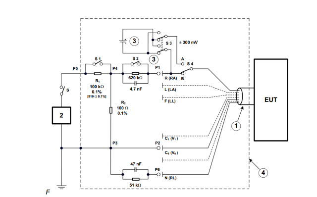
Hello. We have an ECG device with ADS1298R. We need to pass IEC_60601-2-27 and we have some doubts according  sub clause 201.12.1.101.3. It is related to the input impedance measurement. The test is to connect a parallel RC network 620k || 4.7nF in series with tested electrode. 

The idea is to compare the voltage level with and without series impedance. The difference must be less then 20% to pass the test. The test signal is sinus with frequency 0.67Hz and 40Hz.

With 0.67Hz there is insignificant voltage drop, we are passing  the test clearly. With 40Hz we have a voltage drop of about 12%. So we can pass the test, also.

But what I want to know is - why we have this voltage drop on higher frequencies?

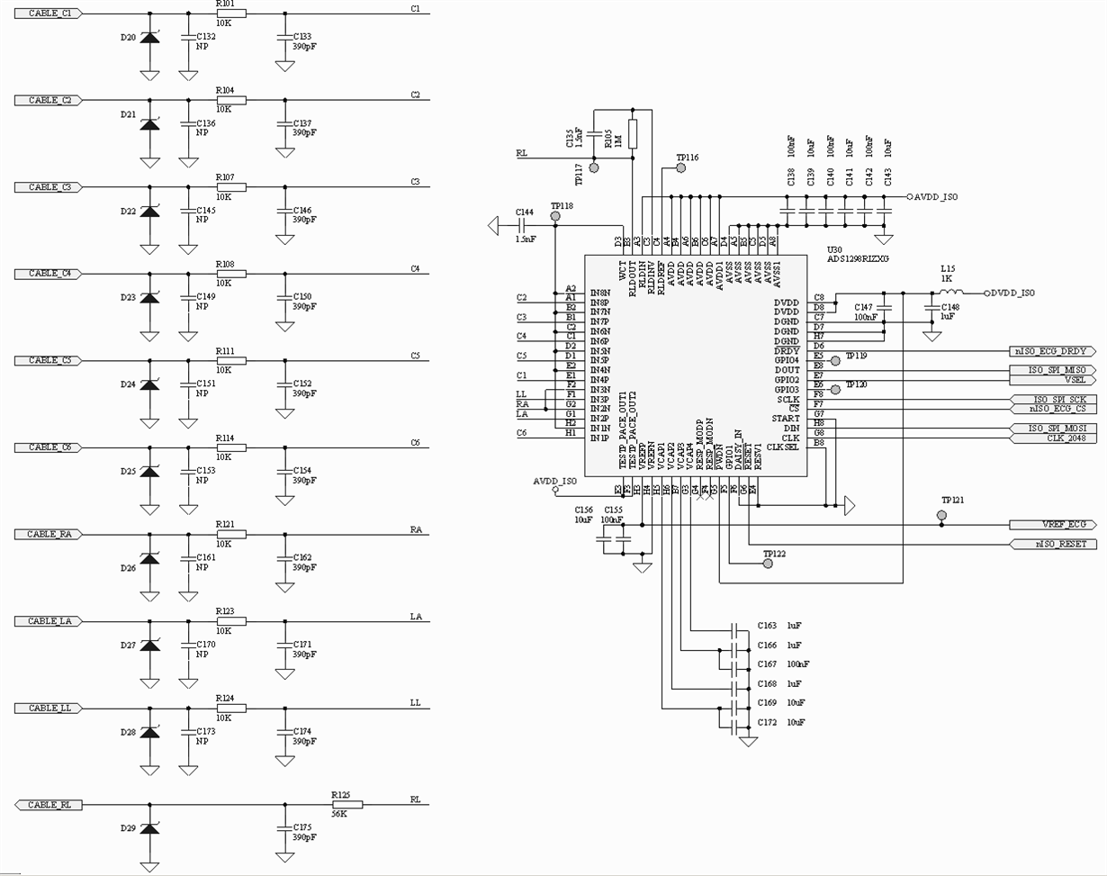
Our input circuit includes simple RC filter 10Kohm || 680pF. We have also a 10Kohm protection in series in the ECG cable. There is a TVS diode in parallel but it's capacitance is really small -few pF. 

So normally the input circuit during the test consists a total resistance of 640kOhm and 700pF capacitance. This is a filter with pole 350Hz. For frequency of 40Hz it should have 0.058dB magnitude decrease, or around 1% amplitude decrease. 

But during my experiments I'm seeing a drop of about 10-12% on 40Hz. And the voltage drop is clearly frequency dependent. On 1Hz we don't have decreasing, on 10Hz becomes visible, on 40Hz it is 10-12%, on 100Hz it is really significant. Due to my simple calculations this is equal to parallel capacitance of about 3nF, which is not existing in my schematics.

We are using active right leg driving. To exclude RLD influence, I'm setting the RLD_SENSP and RLD_SENSN registers to 0x00. This should eliminate a frequency back loop and the RLD amplifier works like a voltage follower, .we are useing it just for body polarization to the middle of the power supply. But we still have the same issue - 40Hz drops with 10-12%.

We have a 2nd order notch filter on 50Hz in the software. But it acts in both cases - with and without 620k connection. The test is relative, so normally this 50Hz notch should not has an impact in test result. Anyway - I tried with 50Hz filter off. There is more noise in this case, but the 40Hz decrease is clearly visible again.

So my question is - what else can provoke this voltage drop on 40Hz when 620kohm is connected in series?

  • Hello Tsvetan,

    Thanks for your post!

    Can you please share a schematic drawing of your input stage to the ADS1298R? It would be easier to review the passive components in the signal path from the electrode to the input pin of each channel.

    Also, what are the register settings that you are using for the ADS1298R? Please provide all settings in hexadecimal format for review. Specifically, I'm curious about the data rate. You may be seeing some additional attenuation from the digital filter. For example, at data rate = 250 SPS, 40 Hz corresponds to 0.16 = fIN / fDATA in Figure 53. The digital filter would attenuate a 40-Hz signal by approximately  -1.15 dB or 12.4% in that scenario.

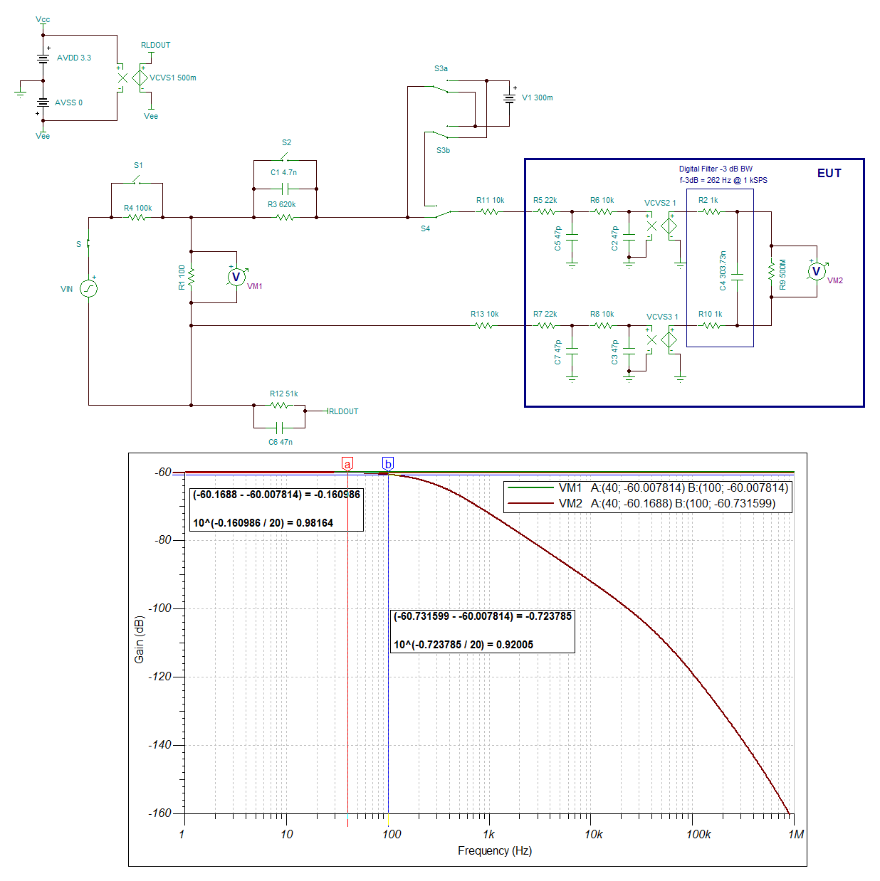
    It may be helpful to simulate the expected signal amplitude at the ADS1298R inputs with a TINA-TI model. Try modifying the attached TINA schematic with the components in your schematic to verify what the expected attenuation should be (for now, ignore the TVS diodes). If you send me your schematic, I can add them to the simulation as well.

    IEC_input_impedance.TSC

    Best Regards,

  • Hello. Here is the input stage of our device. Please take in account that we have additional 10k protection resistor in each electrode lead, not shown on the schematics. The input filter capacitance is 390pF. I wrongly fix it to 680pF in my first post, sorry.

    We use 1Khz sampling rate, High resolution mode, gain 6. The ADS1298R registers are set as follow:

    const uint8_t g_DefaultADS1298Registers[ADS129XX_REG_ENUM] =
    {
    0x00,
    0xC5,          /* HR = ON, DAYSI = OFF, CLK_EN = 0FF, DR = 1000 SPS */
    0x10,          /* WCT_CHOP = var , TEST = INT, TEST_AMP = - ( VREFP - VREFN ) / 2400 V, TEST_FREQ = Fclk/2^21 */
    0xCC,        /* REF_BUFF = ON, VREFP = 2.4V, RLD_MEAS = OFF, RLDREF = ( AVDD-AVSS ) / 2, RLD_BUFF = ON, RLD_LOFF_SENSE = OFF */
    0x03,         /* COMP_TH = 95%, Current source Lead Off Sense, I = 6nA, DC lead off detection */
    0x00,         /* CH1 = ON, GAIN = 6, Normal electrode input */
    0x00,         /* CH2 = ON, GAIN = 6, Normal electrode input */
    0x00,         /* CH3 = ON, GAIN = 6, Normal electrode input */
    0x00,         /* CH4 = ON, GAIN = 6, Normal electrode input */
    0x00,         /* CH5 = ON, GAIN = 6, Normal electrode input */
    0x00,         /* CH6 = ON, GAIN = 6, Normal electrode input */
    0x00,         /* CH7 = ON, GAIN = 6, Normal electrode input */
    0x00,         /* CH8 = ON, GAIN = 6, Normal electrode input */
    0x00,         /* RLD - use it like voltage folower */
    0x00,         /* */
    0xFF,         /* LOFF_SENSP = ON for all channels */
    0x06,        /* LOFF_SENSN - only RA  */
    0x00,        /* LOFF_FLIP = OFF for all channels */
    0x00,        /* */
    0x00,        /* */
    0x00,        /* All GPIOs - outputs with zeroes */
    0x00,        /* Pace off */
    0x20,        /* Respiration off */
    0x02,        /* SINGLE_SHOT = OFF, WCT_TO_RLD = OFF, LEAD_OFF_COMP = ON */
    0x0B,        /* WCTA = RA */
    0xD4        /* WCTB = LA, WCTC = LL*/
    };

  • Hi Tsvetan,

    Thanks for the added details.

    I still do not see a reason why a 40-Hz sine wave is being attenuated so much. Which channels are you measuring the attenuation on, is it on all channels? Does the attenuation look the same when you connect the primary electrodes (RA, LA, and LL) compared to the chest electrodes (V1 - V6)?

    You might also try disabling the lead-off current sources and comparators for now, just to eliminate possible causes. I don't expect this to make a difference.

    Best Regards,

  • Hello Ryan.

    I am measuring such an attenuation (10-12%) on all channels (I, II, V1-V6) on our board. We are using Whailteq SECG 4.0 for signal generation.

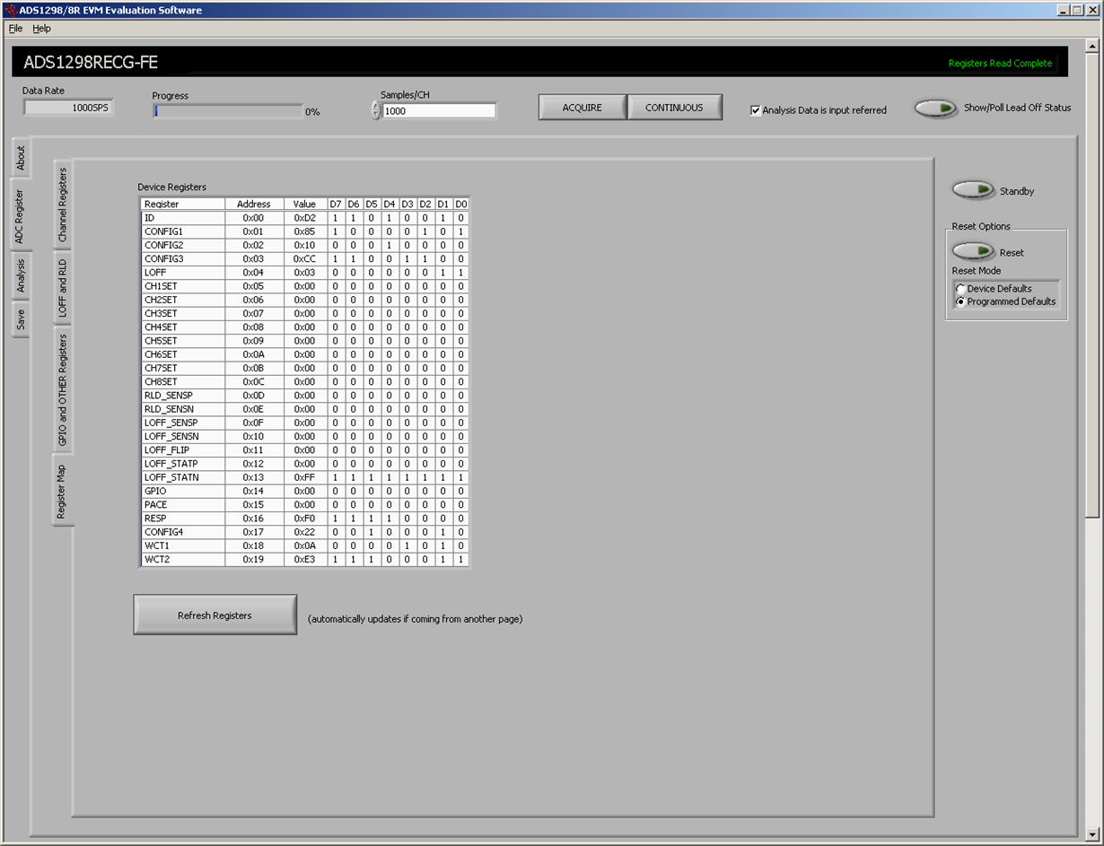
    Anyway to exclude a problem with our device, I made some experiments with ADS1298R  ECGFE development kit. In these experiments I'm seeing approximately the same results:

     1. Input amplitude on the ECG cable (with 10K protection) 8mVpp.

    2. The ECGFE input chain is not changed - i.e. second order RC filer 22K || 47pF and 10K || 47pf.

    3. RA is tested, the measuring channel is 2.

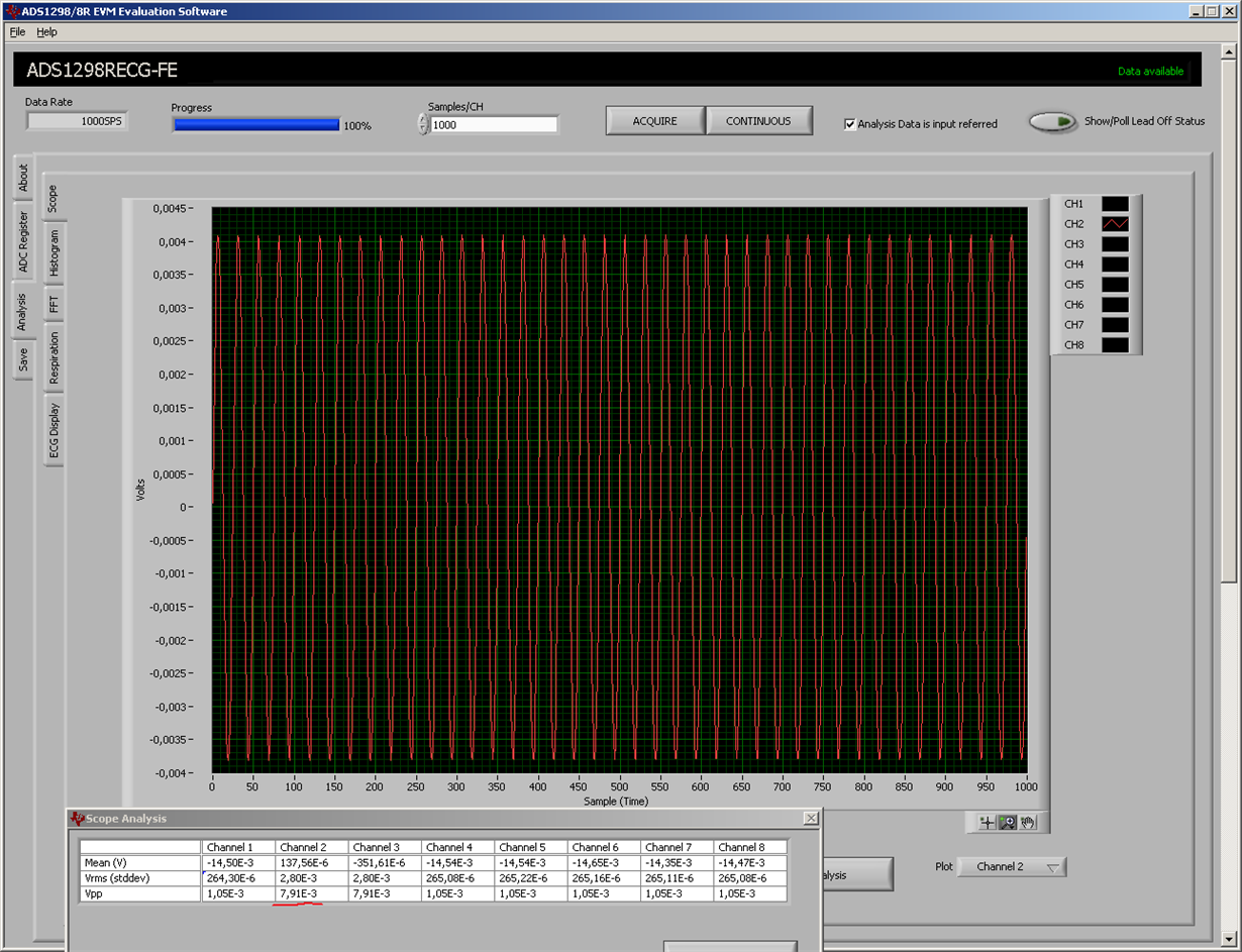
    3. When 620K series resistor is shorted we measure around 7.9 mVpp. See attached pictures.

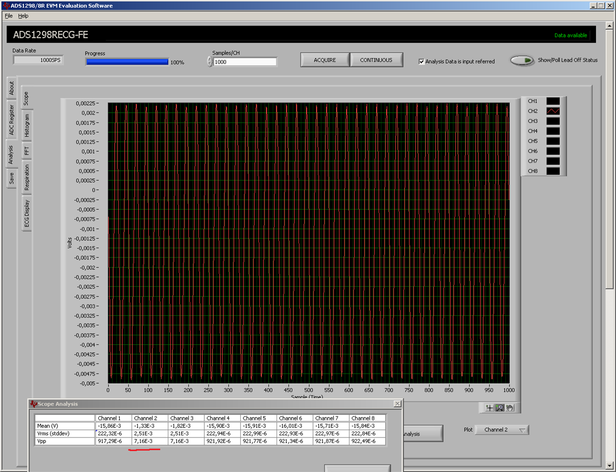
    4. When 620K || 4.7nF  is connected we measure around 7.15 mVpp. See atached pictures.

    5. All experiments are performed via battery powered systems to suppress influence of 50/60Hz from the mains.

    So here we have around 10% attenuation. On development board there is a slight difference when measure other channels. The attenuation varies between 8 and 10%. It is higher in RA and lower on V1-V6.

    I'm sending you a picture with registers set. As you see we use WCT formed by RA, LA and LL. RLD is only polarized on Vsupply / 2. There is no leads in the RLD forming.

    I made one more experiment. When RLD is formed from a set of electrodes (RA, LA... LL), the measured amplitude on 40Hz with 620K in series becomes different in different channels. It goes up and down depending of which electrode is used for RLD forming. But this is normal. Due to 620K in the input, the amplifiers CMR goes crazy. The RLD amplifier is also frequency dependent. So when we return a portion of signal via RLD the amplitude varies also. 

    That's why I think for a clear experiments RLD return path must be limited just to body polarization to Vsupply/2. And in this case we still have an attenuation of about 8-10% on development kit also.

    I made a test with 100Hz input frequency and 2000Hz sampling rate.We have about 25% amplitude decreasing.

    So I still have my question unanswered - why a 620k in series with the input attenuates the input signal so much on 40Hz and even more on 100Hz. What I know for the moment is - the issue is reproduced on development kit, so it's not related to our device.

  • Hello Tsvetan,

    Thanks again for the detailed results - I think these experiments make the issue more clear now.

    One last idea I have is to validate the input signal amplitude at both frequencies with an oscilloscope. You should be able to probe the capacitor at the input of the tested channel to validate the amplitude that the PGA will see (i.e. probe C162 when RA is tested).

    I will try to run the same experiments with an EVM on the bench. Unfortunately, I will be out of the office until next week. If possible, I will ask one of my colleagues to repeat the experiment for me while I'm gone.

    Best Regards,
  • Hello Ryan.

    I will try, but I'm afraid it will not be possible to measure the voltage accurately with a oscilloscope. The signal has a low amplitude. More bad, connecting the oscilloscope ground will introduce a high amount of 50/60Hz noise which makes the an accurate measurement impossible. Due to my experience with ECG signals - It needs a really expensive equipment for such a measurement, which I don't have in fact.

  • Hello Tsvetan,

    Please excuse the delay.

    I was able to repeat the measurements on our bench with the same ADS1298RECGFE-PDK. As a first step, I only used simple wires to connect each electrode input from the DB15 connector to the breadboard where I recreated the input impedance test setup. All electrodes except for RA were shorted together. The RLD output from the EVM was passed through an RC network of 51k || 47nF (according to the test setup). The output of the 51k || 47 nF network was shorted to the electrodes as well as to the negative side of my signal generator. The signal generator was set to 8 Vpp with an offset of 0 V. I swept the frequency from 10 Hz to 100 Hz and never saw a significant change in amplitude (always close to 8 mVpp).

    One difference I had to make in my setup was that I enabled the RLD_SENS bits for channel 2 (RA and LA). This helped me to suppress the 60-Hz noise in the system and get more consistent readings in the peak-to-peak signal output.

    I might have more time this week to repeat the test with real ECG cables, which have 10k - 22k of series impedance in each electrode wire. I have a feeling that the extra attenuation is coming from some passive filter since it is more apparent at higher frequencies.


    Best Regards,

  • Hello Ryan.

    I'm waiting for you results, as you have some.

    But be care - connecting of RIGHT LEG formed by a given set of electrodes in a feedback, changes significantly the test bench. When you connect 620K in series of one input, this makes a common mode rejection of the input PGA to fall extremely low. In this case RLD feedback has a big influence in the 40Hz spectre also. This changes the total schematics gain. I saw it on my test bench - the output amplitude is varies significantly of the exact set of electrodes used in RLD feed back.

    That's why I'm using a RLD only biased on VDD/2. No electrodes path returned in feedback. To reduce noise (which is significant in this case), I'm powering all of my equipment from batteries. I'm also using a grounded table.

  • Understood. I will post some results this afternoon.

    Best Regards,
  • Hi Tsvetan,

    Please see the attached images below.

    Perhaps it is worth noting that the recorded amplitude with S2 open diminished slightly in my results as the input frequency was increased from 10 Hz to 40 Hz to 100 Hz. The total change from 8.22 mVpp to 7.83 mVpp is an attenuation of about 4.7% or -0.42 dB. This attenuation may worsen when S2 is opened; however, in my setup, it is difficult to tell. I believe the additional 60-Hz noise obscured the true amplitude of the input sine wave. The attached results show that the peak-to-peak amplitude increases when S2 is opened for each test frequency. The resulting scope plot clearly shows some additional distortion in the waveform from the 60-Hz noise. So I think for now, the results I was able to collect are still inconclusive with S2 open.

    One point of clarification: PGA in the ADS1298R actually does not contribute anything to the common-mode rejection of the signal chain. Instead,  all of the common-mode rejection occurs in the modulator sampling stage when PGAxN is subtracted from PGAxP (ignoring the effects of RLD for the moment). The PGA is actually comprised of two amplifiers in an instrumentation amp configuration. This is how we are able to sense the common-mode after the PGA by tying each individual PGA amplifier output to a summing junction at the RLD amplifier inverting input.

    IEC_Input Impedance.zip

    Best Regards,

  • Hello Ryan.

    1. Can you specify the exact configuration of RLD feedback for your last experiments. Like I have wrote before, the including of some leads in the right leg feedback significantly changes the amplitude when 40 or 100Hz are measured AND 620k is connected (S2 opened). I have tried various combinations of feedback electrodes (LA+RA, LA+RA+LL and etc.) and I always have a different amplitude in the output, even if other conditions are not changed. Sometimes I have higher amplitude then the source is providing! This means that the RLD feedback has a frequency dependent influence over the total amplification and this effect is mostly visible when S2 is opened (620K connected). My explanation is the common mode rejection ratio, which changes dramatically when the input is unbalanced by the 620K serial resistance. That's why by my opinion is important to make the experiments without any lead included in RLD feedback, just a clear polarization. Of course this makes experiment complicate due to the higher 60Hz noise in this case. 

    2. I'm agree with your explanation of the common mode rejection and PGAs. But I'm looking the system globally. The device has some CMR in ideal case. But the CMS dramatically changes when the input of the system is unbalanced by 620k in one of the differential inputs. Even if the CMR is coming from instrumental amplifier (like traditional ECG schematics) or from the modulator of sigma delta converter (like ADS1298). The end effect is the same - CMR makes worse when the input of the system is unbalanced. Am I right?

  • Hello Tsvetan,

    The configuration I used for RLD feedback was to set bits RLD2P and RLD2N = 1 on the ADS1298RECGFE-PDK. This selected the output of each PGA on Channel 2 such that RA and LA were used to derive the common-mode. I agree with your premise that, if the 620k is included in series with RA, then the RLD feedback may cause the amplitude to change. However, I cannot get a clean enough setup to remove the 60 Hz noise without it and I don't have an option in the software to post-process the data with a notch filter in the Scope tab. The ECG Display tab does show a notch filter setting. You could analyze the peak-to-peak amplitude on Lead I to measure RA against the common electrodes. Unfortunately, there is no Scope Analysis table to calculate that information for you.

    Best Regards,

  • Hello Ryan,
    I am now facing the same problem that needs to compare the voltage level with and without series impedance.,and the difference must be less then 20% to pass the test~
    The frequency is between 0.1Hz to 100Hz,With 0.1Hz there is almost no voltage drop, With 60Hz voltage drop becomes obvious,and the drop out is more than 20% when with 100Hz ,the cutoff freqiency is 1Khz, I don't know why and want to know how to solve it~
    Looking forward to your help,thank you very much~
  • Hello,
    Can I get any suggestion from this post?
    Or I need to create a new post to ask then question?
  • As soon as the problem is exactly the same - I don't thing the new post will help you significantly more. So we are both with unresolved problem now.

    One question - you wrote "cut off frequency 1kHz" - what kind of filtering you are addressing with this phrase? Analog at the input or digital one by software implemented in your device?

  • Hi ,Now the filter value is the same with TI's reference design~
  • Hello Fawn and Tsvetan,

    This has been a difficult issue for us to debug. To summarize, I agree with Tsvetan's point that the signal source must be biased from RLD without using the electrodes in the common-mode derivation loop for reasons explained above.

    Tsvetan - have you tried using a different signal source? I understand you may not have another one which can also be battery powered like the Whaleteq. But this would help us rule out another variable.

    I can look at this again in the lab this week and compare the results from an FFT instead of the Scope tab. Hopefully this is accurate enough to determine that magnitude of the signal at the input frequency apart from any noise that may be present.


    Best Regards,
  • Also, please remember that some attenuation will come from the passive RC filters and the digital filter. I've updated the attached TINA file with the R-C values from the EVM as well as with 10k electrode cable impedance. The attenuation increases from ~1.8% at 40 Hz to ~8% at 100 Hz.

    [E2E] IEC_input_impedance.TSC

    Best Regards,

  • Hello Ryan.

    I will continue to search for another signal source, but as you wrote - it will not be easy to find a noise free system.

    I'm agree with your remarks about in system noise filtering and corresponding attenuation, but it's just a small part of what we see in our experiments (and Fawn too).

  • Hello Ryan & Tsvetan,
    Does this problem have any solutions?
    Can I put an OP circuits to solve the problem?
  • Hello Fawn.

    No - I don't have a reliable solution for the moment. Maybe the OpAmp at the input can help, since it will "cut" the high input impedance from the chip. But this solution (if it works at all) has many drawback - technically it's too complicate - you need many opamp chips. At the same time It must be an OpAmp with a really good parameters, perfectly with a differential input/output, which costs a lot of money and board space. Also with such a way you are loosing the lead off detection integrated in the chip. In fact you are loosing the main advantage of ADS1298 - the integrity of the solution. I'm sure there is other drawbacks which I cannot find now...

    One experiment to try is a test on higher sampling frequency. It is interesting to compare the attenuation on 100Hz with sampling frequency of 1K, 2K and even 4K. But my device doesn't have enough CPU and SPI power to handle such a data traffic...

  • Hello Tsvetan,

    Please find the attached presentation detailing our test setup and results for this thread. Let me know if you have any questions about it. I hope this proves that we've tried to do our due diligence in understanding and reproducing your issue. If you could provide similar results for the same conditions (both Scope and FFT plots), perhaps that'll lead to new information. 

    [E2E] IEC Input Impedance for ADS129x.pptx

    Best Regards,

  • Hello Ryan.

    Let me know - how you perform the test for this presentation - is it a simulation based or a real test with ADS1298 development board and sinus generator?

  • Hi Tsvetan,

    This is real data recorded with an Audio Precision (AP) signal generator and the ADS1298RECGFE-PDK. Through-hole resistors were arranged on a breadboard per the IEC test setup. The AP was connected to the breadboard circuit via banana jack connectors with clips. Inputs to the EVM were connected with wires to the DB15 connector.

    Best Regards,
  • Hello Ryan.

    Your results looks definitively better than mine. Can you give me the ADS1298 register set used in this experiment? Also can you tell me which lead is used for recording the data showed in presentation. 

  • Hi Tsvetan,

    The register settings are on Slide 3. The recorded data is from Channel 2 on the EVM, which is the result of LA (shorted to P2 and all other electrodes) minus RA (shorted to P1). I've updated the presentation below to illustrate the electrode connections. Also, in the TINA schematic and simulation, I made "Rcable" 0 ohms since direct wires were used to connect the test setup to the EVM DB15 connector. This did not change the simulation results.

    1667.[E2E] IEC Input Impedance for ADS129x.pptx

    Best Regards,

  • Hello Ryan.

    I have verified your settings, they cover mine, except lead off detection. On my board it is enabled on all channels with 6nA DC current detection. But this should not affect the measurement significantly,  correct?

  • Hi Tsvetan,

    I was using the settings described in your post from June 5th, shown below. I don't believe this should make a difference as your results taken with the settings below yielded results similar to those from the tests with the settings from May 28th: 

    May 28th Settings:

    const uint8_t g_DefaultADS1298Registers[ADS129XX_REG_ENUM] =
    {
    0x00,
    0xC5,          /* HR = ON, DAYSI = OFF, CLK_EN = 0FF, DR = 1000 SPS */
    0x10,          /* WCT_CHOP = var , TEST = INT, TEST_AMP = - ( VREFP - VREFN ) / 2400 V, TEST_FREQ = Fclk/2^21 */
    0xCC,        /* REF_BUFF = ON, VREFP = 2.4V, RLD_MEAS = OFF, RLDREF = ( AVDD-AVSS ) / 2, RLD_BUFF = ON, RLD_LOFF_SENSE = OFF */
    0x03,         /* COMP_TH = 95%, Current source Lead Off Sense, I = 6nA, DC lead off detection */
    0x00,         /* CH1 = ON, GAIN = 6, Normal electrode input */
    0x00,         /* CH2 = ON, GAIN = 6, Normal electrode input */
    0x00,         /* CH3 = ON, GAIN = 6, Normal electrode input */
    0x00,         /* CH4 = ON, GAIN = 6, Normal electrode input */
    0x00,         /* CH5 = ON, GAIN = 6, Normal electrode input */
    0x00,         /* CH6 = ON, GAIN = 6, Normal electrode input */
    0x00,         /* CH7 = ON, GAIN = 6, Normal electrode input */
    0x00,         /* CH8 = ON, GAIN = 6, Normal electrode input */
    0x00,         /* RLD - use it like voltage folower */
    0x00,         /* */
    0xFF,         /* LOFF_SENSP = ON for all channels */
    0x06,        /* LOFF_SENSN - only RA  */     ** Have you tried reducing the current on RA from 2 x i_LOFF to 1 x i_LOFF? Change to 0x02. **
    0x00,        /* LOFF_FLIP = OFF for all channels */
    0x00,        /* */
    0x00,        /* */
    0x00,        /* All GPIOs - outputs with zeroes */
    0x00,        /* Pace off */
    0x20,        /* Respiration off */
    0x02,        /* SINGLE_SHOT = OFF, WCT_TO_RLD = OFF, LEAD_OFF_COMP = ON */
    0x0B,        /* WCTA = RA */
    0xD4        /* WCTB = LA, WCTC = LL*/
    };

    June 5th Settings:

    Best Regards,

  • Hello,Ryan,

    Can you help  to use below settings to see the difference?Thank you very much~

    As my E2E post link:

    define     ADC_CH_SET_ON_1          (0x0010u)

    #define     ADC_CH_SET_ON_6          (0x0000u)

    #define     ADC_CH_SET_ON_12          (0x0060u)

    #define     ADC_CH_SET_OFF          (0x0090u)

    #define     ADC_CH_SET_MUX_OUT          (0x0000u)

    #define     ADC_CH_SET_MUX_TSIG          (0x0005u)

    #define     ADC_CH_SET_MUX_TMP          (0x0004u)

    //#define     ADC_CH_SET                  ADC_CH_SET_ON_6 | ADC_CH_SET_MUX_TSIG

    #define     ADC_CH_SET                  ADC_CH_SET_ON_6

    /* ADC 1 parameter data */

    #define    ADC1_TYPE                         ADS1298

    #define    ADC1_SERPORT                      (1)

    #define    ADC1_ADS1298DEVID                 (0x0000u)

    //#define    ADC1_ADS1298CONFIG1               (0x0085u)/* sample rate 1000 */

    #define    ADC1_ADS1298CONFIG1               (0x0084u)/* sample rate 2000 */

    //#define    ADC1_ADS1298CONFIG1               (0x0083u)/* sample rate 4000 */

    //#define    ADC1_ADS1298CONFIG2               (0x0000u)/* Internal test*/

    #define    ADC1_ADS1298CONFIG2               (0x0015u)/* Internal test */

    //#define    ADC1_ADS1298CONFIG3               (0x00DCu)

    #define    ADC1_ADS1298CONFIG3               (0x00EFu)

    //#define    ADC1_ADS1298LOFF                  (0x0003u)

    #define    ADC1_ADS1298LOFF                  (0x00E3u)

    #define    ADC1_ADS1298CH1SET                ADC_CH_SET

    #define    ADC1_ADS1298CH2SET                ADC_CH_SET

    #define    ADC1_ADS1298CH3SET                ADC_CH_SET

    #define    ADC1_ADS1298CH4SET                ADC_CH_SET

    #define    ADC1_ADS1298CH5SET                ADC_CH_SET

    #define    ADC1_ADS1298CH6SET                ADC_CH_SET

    #define    ADC1_ADS1298CH7SET                ADC_CH_SET

    #define    ADC1_ADS1298CH8SET                ADC_CH_SET

    //#define    ADC1_ADS1298RLDSENSP              (0x0000u)

    //#define    ADC1_ADS1298RLDSENSN              (0x0000u)

    //#define    ADC1_ADS1298RLDSENSP              (0x0030u)

    //#define    ADC1_ADS1298RLDSENSN              (0x0020u)

    #define    ADC1_ADS1298RLDSENSP              (0x00FFu)

    #define    ADC1_ADS1298RLDSENSN              (0x00FFu)

    //#define    ADC1_ADS1298LOFFSENSP             (0x00FFu)

    //#define    ADC1_ADS1298LOFFSENSN             (0x0002u)

    #define    ADC1_ADS1298LOFFSENSP             (0x00FFu)

    #define    ADC1_ADS1298LOFFSENSN             (0x0001u)

    #define    ADC1_ADS1298LOFFFLIP              (0x0000u)

    #define    ADC1_ADS1298LOFFSTATP             (0x000FFu)

    #define    ADC1_ADS1298LOFFSTATN             (0x0003u)

    #define    ADC1_ADS1298GPIO                  (0x0001u)

    #define    ADC1_ADS1298PACE                  (0x0001u)

    #define    ADC1_ADS1298RESP                  (0x0000u)

    #define    ADC1_ADS1298CONFIG4               (0x0002u)

    #define    ADC1_ADS1298WCT1                  (0x0009u)

    #define    ADC1_ADS1298WCT2                  (0x00C2u)

    //#define    ADC1_ADS1298WCT1                  (0x000Au)

    //#define    ADC1_ADS1298WCT2                  (0x00E3u)

    Another Question:

    As is described in ADS1298's datasheet,DC input impedance can be 500MΩ in current source lead-off detection,I'd like to know how to get the 500MΩ in  your test?