This thread has been locked.

If you have a related question, please click the "Ask a related question" button in the top right corner. The newly created question will be automatically linked to this question.

SRIO Help for Beginners (C6678 and SRIO switch)

Hello,

First, I don't often give praise for support but I must say Travis, Karthik and Derek from TI have been extremely instrumental in getting my SRIO environment to work and bringing me up to speed on tips and tricks for SRIO.  It has been very nice to see success and progress.  Thanks again guys!

So in an effort to consolidate much of what I have learned, I will post here some information that I would have found extremely helpful 5 weeks ago :)

My environment:

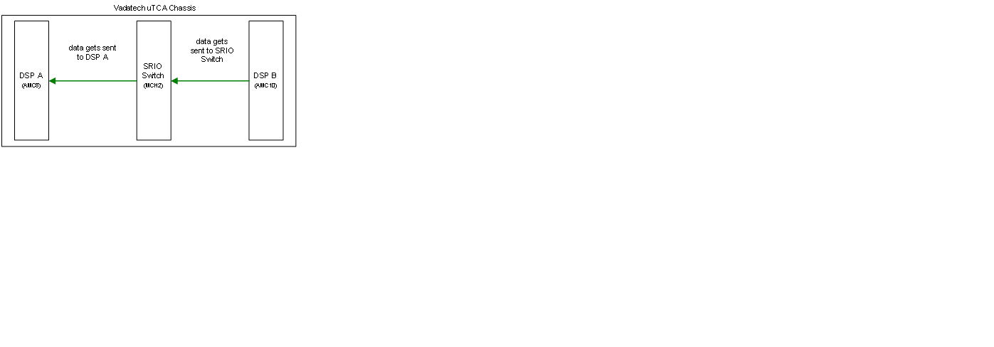
I was using a aTCA chassis with a MCH that has an SRIO switch.  For more on my setup, please see this post: http://e2e.ti.com/support/dsp/c6000_multi-core_dsps/f/639/t/164695.aspx  Here I say what parts I am using and some commands that I found helpful when working with the MCH.


My Goal:

Get DSP-A on C6678 EVM-A to send a message to DSP-B on C6678 EVM-B via an SRIO switch.


TI Example Programs:

When the TI programs are in loopback mode, they seem to work just fine.  They use the CSL (Chip Support Library) to access registers.  The CSL is nice.  Plus once you open a CSL handle, you can just access the structure with all the registers yourself (see example in the after port ok section).

To switch between loopback and "normal" mode use these CSLs:

CSL_SRIO_SetLoopbackMode(hSrio, 0);

CSL_SRIO_SetNormalMode(hSrio,0);

While it seemed to make sense for me to use the MultiCoreLoopback example or the ChipToChip example, it turns out these are extremely complex and make it difficult to learn/understand what is going on. 

Travis recommended using the loopbackDioIsr example project.  This project is simpler using less of the queuing capabilities of the dsp.  This program essentially accesses an exact memory location as given in the LSU (load storage unit) registers at the destination ID.  So in the case of a loopback, it is just another location in DSP-A.  In normal mode, it is a memory location in DSP-B (assuming you set up the destination IDs).  Be careful, this also means you can write to any location in memory - any!

Switch and routing issues:

- Remember all device ids have to be unique.  So if you use the same example program on each DSP (A&B), it won't work unless you change the device ids.

- Remember that the switch will need to be configured to properly route destination ids on the packets.  This can be done with maintanence packets or by direct configuration of the switch.  In my case, the switch has a default configuration file that I modified to route from DSP-A to DSP-B. 

- Remember to make sure that the switch enables the input and output on the port you are using.  If it is not enabled only maintanence packets will be received.  All other types will be dropped.

- my switch could only accept one connection from one device ID.  The way the TI SRIO works is that you can have multiple port connections but they will always have the same device ID.  The examples are written to make (4) 1 lane connections to the other device.   You might need to adjust this portion of the examples if your switch is like mine.

- Travis says "port-writes" should be disabled unless you have a specific reason to use them.

- some switches need to be specially enabled to accept 16 bit destination ids.  Just something to keep in mind.

Understanding Ack IDs (from Travis):

Normal handshaking at the physical layer would be like this: 

Device A sends a packet to Device B with ackid n

There is a transmission error on packet ackid n

Device B sees a CRC error and goes into Input error stopped state
(drops all new RX packets)

Device B sends a PNA control symbol to Device A

On reception of the PNA, Device A goes into output error stopped
state (stops sending any new packets)

Device A sends a LR Input status control symbol to device B

On reception of the LR input status, Device B sends a Link
maintenance response control symbol indicating packet ackid n was the PNA
packet.

Also, Device B then enters normal mode.

On reception of the link maintenance response packet, Device A goes
into normal mode and starts resending packets to device B stating with packet
ackid n

Things to check after "Port Ok":

After you get a port ok, if you are having problems sending messages here are some registers you should check (the listed register is for Port 0).

- ERR_Stat (TI register 0xB158)

- LM_RESP (TI register B144)

- ERR_Det (TI register C040)

- SP0_CTL (TI register B15C)

These collectively told me that the switch was not accepting my packets and in the end lead to the discovery that the switch had not enabled input and output messaging and was only accepting maintanence packets.

If you ever see the Output Error Stop condition or the Input Error Stop condition, there is a magic number that is to be written to a register.  In fact, Travis recommends doing this no matter what after receiving "Port Ok".

hSrio->RIO_PLM[i].RIO_PLM_SP_LONG_CS_TX1 = 0x2003F044;

System_printf("SRIO (Core %i): Correct Output Error Stop Condition.\n", coreNum);

After you have sent messages using the LSU, there is an LSU status register that is very helpful for indicating if the transfer was good or not.

Maintenance Packets:

Here is a short blip of code that I wrote to read a register from the switch via a maintanence packet.  this function will work with the dioIsr example.  Sorry about the formatting.

static Int32 maintanenceReadReg(Srio_SockHandle handle, UInt32 srioReg)

{

Srio_SockAddrInfo       to;

uint16_t                compCode;

uint16_t                counter;

int32_t                 startTime;

UInt8 * pReadRespBuf = NULL;

UInt8 * pTmpRead = NULL;

pReadRespBuf = (uint8_t*)Osal_srioDataBufferMalloc(4);

if(pReadRespBuf == NULL)

{

System_printf("Error: pReadRespBuf Memory allocation failed.\n");

}

pTmpRead = pReadRespBuf;

for (counter = 0; counter < 4; counter++)

    {

    *pTmpRead++ = 0x55;

    }

to.dio.rapidIOMSB    = 0x0;

to.dio.rapidIOLSB    = srioReg; //0x0015C;//(uint32_t)&dstDataBufPtr[srcDstBufIdx][0];

to.dio.dstID         = DEVICE_ID4_8BIT;

to.dio.ttype         = 0; //Read

to.dio.ftype         = 8; //Maintanence packets

/* Send the DIO Information. */

if (Srio_sockSend_DIO (handle, pReadRespBuf, 4, (Srio_SockAddrInfo*)&to) < 0)

{

System_printf ("Error: (Core %d): Could not send message.\n", coreNum);

return -1;

}

/* Wait for the interrupt to occur without touching the peripheral. */

/* Other useful work could be done here such as by invoking a scheduler */

startTime = TSCL;

while((! srioLsuIsrServiced) && ((TSCL - startTime) < SRIO_DIO_LSU_ISR_TIMEOUT));

if (! srioLsuIsrServiced) {

  System_printf ("ISR didn't happen within set time - %d cycles. Example failed !!!\n", SRIO_DIO_LSU_ISR_TIMEOUT);

return -1;

}

Osal_srioDataBufferFree(pReadRespBuf, 4);

return 0;

}

Calling the function:

maintanenceReadReg(mySrioSocket, 0x15C);

CSL_SRIO_ClearLSUPendingInterrupt (hSrioCSL, 0xFFFFFFFF, 0xFFFFFFFF);

srioLsuIsrServiced = 0;

This clearingLSUPending interrupt is important - it has to happen after each transmission (at least in this example). 

Various Other Posts to check:

http://e2e.ti.com/support/dsp/c6000_multi-core_dsps/f/639/t/168310.aspx

http://e2e.ti.com/support/dsp/c6000_multi-core_dsps/f/639/p/180758/652988.aspx#652988

http://e2e.ti.com/support/dsp/c6000_multi-core_dsps/f/639/t/167006.aspx

http://e2e.ti.com/support/dsp/c6000_multi-core_dsps/f/639/t/165949.aspx


I am sure I have forgotten a few things but hopefully this will get you started and post away, hopefully Travis, Derek or Karthik will see it and be able to help!


Good luck!


Brandy

PS - thanks again guys, it feels great to be moving forward!!


  • Just wanted to be able to click the verify button :)

  • Hello,


    Here is another document to reference describing in better detail the Stop Error Condition Fix and the ACKID alignment procedure.  It is a TI draft and should be regarded as such, but it worked for me.

    6557.Keystone Software Assisted Error recovery_addendum.pdf


    Also, here is my function for obtaining the ackID (from the switch) and then assigning it to the DSP registers.  Once the inboundAckID is obtained, use a maintanence write action to write it to the switch (as described in the above doc.)

    int32_t srioAlignAckIDs(void)

    {

    CSL_SrioHandle hSrio;

    int32_t inboundAckID = 0;

    hSrio = CSL_SRIO_Open (0);

    inboundAckID = (hSrio->RIO_SP[0].RIO_SP_LM_RESP & 0x000003E0) >> 5;

    hSrio->RIO_SP[0].RIO_SP_ACKID_STAT = (inboundAckID | (inboundAckID << 8) | ((inboundAckID+1) << 24));

    return inboundAckID;

    }

  • Hi Brandy,

    What you have written above really helps me a lot. However, actually, I'm using EVM6670 to do some work on it, and I also want to use SRIO port to comunicate with FPGA. Unfortunately, I have not got the FPGA board already but have to write some programs to make sure it will work when the FPGA board is done - my boss told me,  and by that time I only need to modified some particular port addresses or so. Fortunately, I have done some work according to your support above including

    1.Disable the digital loopback and put the SRIO in normal operation.

    2.Change path mode to 1 port 4x mode.

    3.Add the function-static Int32 maintanenceReadReg() to read a register from the switch via a maintanence packet. 

    4.Add the function-int32_t srioAlignAckIDs() to obtain the ackID (from the switch) and then assigning it to the DSP registers.

    And then I don't what to do with my dioIsr program, please do help me with the following questions:

    1.Is there any other things should be modified in the diolsr example?

    2.How to write a socket and how to use this program to send it?

    3.When communicating with the FPGA board, how to make sure the things goes right and how can I check it?

    Thanks

    Tom Hua.

  • Hua,

    The way I use SRIO is with a direct write to memory.  To test without my FPGA, I got a second EVM and created a test program to write to the memory of the first EVM.

    The only way to know that the data was written is to have DSP B send a doorbell to DSP A when it is finished writing data.  There are some registers that can be polled too, you can find them in the SRIO configuration doc, sprugw1a.  You can then either write a program for DSP A to verify that it got the correct data or just look at the memory location and see that it is correct.

    Like this:

    The program on DSP B uses code similar to below.  It won’t compile in this form but you get the idea.  If you want to do some other sort of messaging, you’ll have to figure that on your own.


    Srio_SockHandle myOpenSrioSocket(Srio_DrvHandle hDrv, Srio_SockBindAddrInfo * bind)

    {

        Srio_SockHandle mySocket = NULL;

        char            buffer[MAX_MESSAGE_SIZE];

        mySocket = Srio_sockOpen (hDrv, Srio_SocketType_DIO, FALSE);

        if (mySocket == NULL)

        {

            sprintf(buffer, "Unable to open the DIO socket" );

            ekg_vfib(buffer, CORE0_MAIN_TASK, CORE0_MAIN_TASK);

            return NULL;

        }

        /* Bind the SRIO socket: DIO sockets do not need any binding information. */

        if (Srio_sockBind_DIO (mySocket, bind) < 0)

        {

            sprintf(buffer, "Binding the SIO socket failed.");

            ekg_vfib(buffer, CORE0_MAIN_TASK, CORE0_MAIN_TASK);

            return NULL;

        }

        return mySocket;

    }

        bindInfo.dio.doorbellValid  = 0;  // send a doorbell after last packet

        bindInfo.dio.intrRequest    = 1;

        bindInfo.dio.supInt         = 0;

        bindInfo.dio.xambs          = 0;

        bindInfo.dio.priority       = 0;

        bindInfo.dio.outPortID      = 0;

        bindInfo.dio.idSize         = 0;//1; //1 = 16 bit, 0 = 8 bit;

        bindInfo.dio.srcIDMap       = 0;

        bindInfo.dio.hopCount       = 0;

        bindInfo.dio.doorbellReg    = 0;  //Doorbell0_ICR[0]

        bindInfo.dio.doorbellBit    = 0;  //Doorbell0_ICRR[3:0]

    for (counter = 0; counter < NUM_TRANSFERS; counter++)

                {

                    hSrioSock = myOpenSrioSocket (hSrioDrv, &bindInfo);

                    if (hSrioSock == NULL)

                    {

                      LOG_ERROR ("Unable to open the srio socket for transmitting image");

                      return -1;

                    }

                    /* Populate the DIO Address Information where the data is to be sent. */

                    to.dio.rapidIOMSB    = 0x0;

                    to.dio.rapidIOLSB    = (UInt32)&windows[0][0] + 256*counter + BUFFER_SIZE*i;//(uint32_t)&dstDataBufPtr[srcDstBufIdx][0];

                    to.dio.dstID         = REMOTE_ID1_8BIT;//DEVICE_ID4_8BIT;

                    to.dio.ttype         = dio_ttype;

                    to.dio.ftype         = dio_ftype;

                    /* Send the DIO Information. */

                    if (Srio_sockSend_DIO (hSrioSock, (Srio_DrvBuffer)&windows[i][256*counter], 256, (Srio_SockAddrInfo*)&to) < 0)

                    {

                        LOG_ERROR ("Send image chunk failed. %i",counter);

                        return -1;

                    }

                    /* Wait for the interrupt to occur without touching the peripheral. */

                    /* Other useful work could be done here such as by invoking a scheduler */

                    while((! srioLsuIsrServiced) );

                    /* Read the completion code filled by the ISR */

                    compCode = 0xFF;

                    if (Srio_getSockOpt(hSrioSock, Srio_Opt_DIO_READ_SOCK_COMP_CODE, &compCode, sizeof(uint8_t)) < 0)

                    {

                        LOG_ERROR ("Unable to read the completion code in socket");

                        return -1;

                    }

                    /* Was the transfer good. */

                    if (!compCode == 0)

                    {

                        LOG_ERROR("Transfer was bad, code = 0x%x.", compCode);

                    }

                    /* Clear the LSU pending interrupt (ICCx) */

                    CSL_SRIO_ClearLSUPendingInterrupt (hSrioCSL, 0xFFFFFFFF, 0xFFFFFFFF);

                    srioLsuIsrServiced = 0;

                    Srio_sockClose(hSrioSock);

                    int Override;

                    Override = 5; //i; //controls whether the doorbell is fixed or rotating.

                    if(counter == (NUM_TRANSFERS-1)) //last packet

                    {

                        bindInfo.dio.doorbellValid  = 1;  // send a doorbell after last packet

                        bindInfo.dio.doorbellBit    = Override;//i;  //Doorbell0_ICRR[3:0]

                        hSrioSock = myOpenSrioSocket (hSrioDrv, &bindInfo);

                        if (hSrioSock == NULL)

                        {

                            LOG_ERROR ("Unable to open the srio socket for transmitting header.");

                          return -1;

                        }

                        /* Populate the DIO Address Information where the data is to be sent. */

                        to.dio.rapidIOMSB    = 0x0;

                        to.dio.rapidIOLSB    = (UInt32)&windows[0][0] + 256*counter + BUFFER_SIZE*i;//(uint32_t)&dstDataBufPtr[srcDstBufIdx][0];

                        to.dio.dstID         = REMOTE_ID1_8BIT;//DEVICE_ID4_8BIT;

                        to.dio.ttype         = dio_ttype;

                        to.dio.ftype         = dio_ftype;


                        /* Send the DIO Information. */

                        if (Srio_sockSend_DIO (hSrioSock, (Srio_DrvBuffer)&imgHdrs[i], 6*sizeof(unsigned int), (Srio_SockAddrInfo*)&to) < 0)

                        {

                            LOG_ERROR ("Send srio header failed.");

                            return -1;

                        }

                        /* Wait for the interrupt to occur without touching the peripheral. */

                        /* Other useful work could be done here such as by invoking a scheduler */

                        while((! srioLsuIsrServiced) );

                        /* Read the completion code filled by the ISR */

                        compCode = 0xFF;

                        if (Srio_getSockOpt(hSrioSock, Srio_Opt_DIO_READ_SOCK_COMP_CODE, &compCode, sizeof(uint8_t)) < 0)

                        {

                            LOG_ERROR ("Unable to read the completion code in socket");

                            return -1;

                        }

                        /* Was the transfer good. */

                        if (!compCode == 0)

                        {

                 //           LOG_ERROR("Transfer was bad, code = 0x%x.", compCode);

                        }

                        /* Clear the LSU pending interrupt (ICCx) */

                        CSL_SRIO_ClearLSUPendingInterrupt (hSrioCSL, 0xFFFFFFFF, 0xFFFFFFFF);

                        srioLsuIsrServiced = 0;

                        Srio_sockClose(hSrioSock);

                    }

                }

  • Brandy,

    Thank you so much for your help, I will see through the program and do some more work about the  the SRIO configuration doc, sprugw1a. Actually, I have read a lot about it but had found so many errors in it and I don't know what to do with the errors. Do you know some modified SRIO configuration docs? Thank you.

    Tom Hua

  • I have posted some of the typos that I found, I think it a post literally called Typos in SPRUGW1A.  Generally though, if I thought it was a typo, I posted it in a forum for confirmation.  TI is very good to respond.


  • Hi, Brandy,

    Your post is really very helpful. Thanks a lot. I'm now also trying to make two C6678 EVM boards talk through SRIO, although the final goal is DSP talk to FPGA.

    In your case you have SRIO switch. My question is: can I directly connect the two EVM boards to perform the test? Like:

    (board1)tx+ => (board2)rx+, (board1)tx- => (board2)rx-, (board2)tx+ => (board1)rx+, (board2)tx- => (board1)rx-

    I have two AMC-SMA boards for the connection.

    Thanks.

    Weiyi


  • Hi Tang,

    This seems like a hardware question.  That is not my speciality, I am good with software :).  I recommend reposting your question the C6678 forum.  I think you will get a response quicker.


    Thanks,
    Brandy

  • Thanks for your quick response, Brandy. I'll it.

  • Hi BrandyJ

    Im trying to connet EVM6678 with a fpga using lane 3, but I just cannot figure out how to configure the socket to a specific lane or port. Im wondering how the socket works.

    Many thanks

  • Hi Fei,

    I'd liked to help, but can you start another post for this? This post is pretty much closed and with a new post someone from TI might be able to answer too.  Unfortunately, I don't have privileges to move posts :)  Once I see this as its own post, I'll see what I can do :)

    Thanks,

    Brandy

  • First of all thanks for such a great explanation, it clears most of the doubts. Here I got one doubt as you explained:

    "Remember that the switch will need to be configured to properly route destination ids on the packets.  This can be done with maintanence packets or by direct configuration of the switch.  In my case, the switch has a default configuration file that I modified to route from DSP-A to DSP-B."

    Is this mean configuration before initialization or after initialization? Can you please post the configuration details for the switch?


    Thanks & Regards

    Ashish Khetan


  • Ashish,

    Sorry about the delay.  This got lost in my inbox.

    Do you still need advice? 

    What I meant was that I was using NAT MCH with a TSI577 SRIO switch in it.  NAT was kind enough to provide a configuration file on the MCH that set up the switch upon MCH power on.  If you do not have an MCH, I think this will most likely not be an option for you.

    Instead (which I also did later), you will have to configure the switch with maintenance packets.  This will occur immediately after getting a PORT_OK and syncing the ACK_IDs on the switch and the DSP.  Once the ACK_IDs are aligned you can send any number of maintenance packets to configure the routing table on the switch.

    Again, sorry so late.  Let me know if you still need more advice.

    Brandy

  • Hi  BrandyJ

    Did u ever tried SRIO Enumeration in 6678...

    Planning to design a board with multiple 6678 chips  along with a SRIO switch

    How to do SRIO enumeration in this case ?

  • Hi Mahendra,

    What do you mean by SRIO Enumeration?

    I have a custom board with many DSP and 1 switch.  I have a routine that can enumerate the one switch and everything attached to it and sets up the switches routing table.

    I use the maintance packets and adjust the hop count.  Adjusting the hop count I think is clear logic, what was tricky, is that even if you change the hop count you also have to make sure that response packet can be routed all to the enumerator. 

    For example, if you are sending the maintance packets out from srcID D1 with hop count 2, you have to make sure that the route for D1 was set up previously (ie from device at hop count 1 and device at hop count 0).

    Brandy

  • Hi Brandy

    Can you please attach the reference routine that can enumerate the one switch and everything attached to it and sets up the switches routing table ? Please help ...

    I have one another situation that multiple boards will be placed in the slots

    for example a board contains 2 nos of 6678 DSP and one nos of CPS1432 switch .. Similar boards will be placed in the vpx slot

    So the first board device should enumerate not only the first board devices but also the other board devices which is connected thru back plane.. is that possible ?

    Thanks

    Mahendra


  • Mahendra varman said:
    So the first board device should enumerate not only the first board devices but also the other board devices which is connected thru back plane.. is that possible ?

    It is certainly possible to do this, but not easily.  I had started to write a totally dynamic routine to enumerator unlimited switches etc, but it proved too tedious and not worth the potential memory needed for storing routing tables as I create them etc..  I also did not have the time.

    I cannot give you my code, but I'll try to guide you.  I believe the code for sending a maintance packet is already listed.  My original guide for enumaterion was this link:

    http://www.edn.com/design/systems-design/4324420/Software-considerations-around-RapidIO-designs

    Since each of my endpoints has an ID already, mine route was discovery.  However, enumeration is not much more difficult because you just send a maintaince packet that sets the ID instead of one that reads the ID. 

    Here is some steps and hints that might help you get started from reading through my algorithm:

    1.  Open sockets with the proper hop count.  Since I only had a max hop count of 3, I open them all up from the start, but you can also do this dynamically as you increase the hop count.

    2.  The first thing the enumerator needs to do is make sure the ACKIDs are aligned with the switch.  It cannot send any maintance packets unless this is the case.  See above.

    3.  Once aligned, I merely test to see if the switch will respond using register 0x010.  This register tells me if I am attached to a switch or endpoint.

    4.  If its a switch, I get my port information so I know what port I am on.  (using 0x014).

    5.  Once I know what port I am on, I can set up my return route on the switch.  Here is the example.

    			LOG_INFO("1. Setting Routing table entry on Switch.  Send 0x%x to port %i.", myDeviceId, myPortOnSwitch);
    			maintanenceWriteReg(srioSocket0, 0x70, 0x00, 0x00, 0x00, myDeviceId, SRIO_BROADCAST_ID); //write device id
    			maintanenceWriteReg(srioSocket0, 0x74, 0x00, 0x00, 0x00, myPortOnSwitch, SRIO_BROADCAST_ID); //write port to associate

    6.   I use the Lock register to know if I have already set up the routing table already (0x068) or if another device is setting up the routing table.  I use this register kind of like a semaphore.

    7.  Once I get the lock register, I enable all the ports on the switch.

    8.  Then I increase the hop count by one and send packets through the switch (remember you set up the routing table to route through the switch and back to you).  I again use the 0x010 register to see what is attached to the switch (more switches or more endpoints).  For endpoints I read the device id and port to set the switch's routing table.  If I discover new switches I need to store where they are on the original switch and go back and discover those separately with an increase in the hop count.  Here is a small incomplete part of this step to get you thinking:

    LOG_INFO("1. Attempting to discover rest of network.");
    			for(i = 0; i < numPortsOnSwitch; i++)
    			{
    				maintanenceReadReg(srioSocket0, 0x158+0x20*i, SRIO_BROADCAST_ID, &readResponse);
    				portStatus = readResponse;
    				if( (i != myPortOnSwitch) && (portStatus & 0x00000002)) //if not my port and PORT_OK
    				{
    					LOG_DEBUG("1. Looking on Port %i",i);
    					//Change entry for 0xFF to next port.
    					maintanenceWriteReg(srioSocket0, 0x70, 0x00, 0x00, 0x00, SRIO_BROADCAST_ID, SRIO_BROADCAST_ID);
    					maintanenceWriteReg(srioSocket0, 0x74, 0x00, 0x00, 0x00, i, SRIO_BROADCAST_ID);
    
    					maintanenceReadReg(srioSocket1, 0x010, SRIO_BROADCAST_ID, &readResponse);

    9.  I repeat this routine for up to a chain of two switches (since I know that is our projects max.)  You would have to do this dynamically for your setup if you do not know exactly what your routes will be.

    Your switch's manual should have all the registers listed.  They have all the information necessary to the discovery.  It is just hard to get it all to align (ack ids, routing table, hop count.)  You have to be very diligent.

    Hope this helps.  

    Brandy J 

  • Brandy,

    Not sure if you are still monitoring these forums, but you "Help for beginners" has been helpful.  Thank you.

    If you have a chance, I'd appreciate a quick glance at the following post and any thought you might have.

    Mike

    https://e2e.ti.com/support/dsp/c6000_multi-core_dsps/f/639/t/412953

  • Hi Brandy, I am now doing some work on EVMk2H and I would like to connect two K2H with SRIO switch. I am confused which type of chassis to choose. So I would like to know which chassis you choose or you recommend. Thanks!
  • mark & thanks, it is really useful for beginners.