Because of the Thanksgiving holiday in the U.S., TI E2E™ design support forum responses may be delayed from November 25 through December 2. Thank you for your patience.

This thread has been locked.

If you have a related question, please click the "Ask a related question" button in the top right corner. The newly created question will be automatically linked to this question.

DM814x/DM816x interface to monochrome CCD Sensor

All,

    We would like to use the DM814x/816x interface to 2 monochrome CCD sensors, each sensor module outputs 16 bit raw data with pixel clock, Line sync and frame sync.

we want to know how the sensor modules interface to HDVPSS and how to setup HDVPSS.

 Thanks.

John

  • Hi,

    DM814X can not support two 16-bit. The below are supported input formats.

    Input Ports and Sharing of the 24-Bit Data Bus
    The VIP parser supports two independent pixel clock input domains: Port A and Port B. Port A supports a
    single 24-bit data bus at the instance level. Port B supports a single 8-bit data bus at the instance level.
    For the device, a single set of 24 device pins are used to drive both Ports A and B.
    The two VIP instances are not identical from the chip level. VIP instance 0 is a 24-bit interface and VIP
    instance 1 is a 16-bit interface. The configuration for each device input port is described in Table 2-6.
    Each port can individually be configured as Discrete Sync or Embedded Sync.

    Valid Input Port Configurations

    Port A Port B
     8 Bit  Off
    16 Bit  Off
    24 Bit  Off
     8 Bit  8 Bit
     Off   8 Bit

    Regards,

    Hyun

  • Hi Liu,


    You could use VIP0 and VIP1 to connect two 16bit RAW sensors, but there is no module in HDVPSS to convert RAW to YUV.


    regards,

    Brijesh

  • Hi,

    I have the same configuration with DM8148 (PG_3.0), except monochrome 12 bit raw pixels (Aptina AR0132AT). And I don't want any format conversions.

    I have analyzed the "av_bios_sdk v00_08_00_00" demo which captures the MT9M024 sensor. It is also a 12bit sensor, but with RGB Bayer option.

    I am confused about the HDVPSS capture configuration:.
    createArgs->videoCaptureMode = VPS_CAPT_VIDEO_CAPTURE_MODE_SINGLE_CH_NON_MUX_DISCRETE_SYNC_HSYNC_VSYNC;
    createArgs->videoIfMode = VPS_CAPT_VIDEO_IF_MODE_16BIT;
    createArgs->inDataFormat = FVID2_DF_YUV422P;
    The VIN parser expect YUV422 frames, but the sensor has a 12 bit RGB format. How it works? Is it a workaround, because there is no raw input format supported from the HDVPSS driver?

    createArgs->inScanFormat = FVID2_SF_INTERLACED;
    Here the same. The sensor produces progressive frames.

    pOutInfo->dataFormat = FVID2_DF_YUV422I_YUYV;
    This is an output format for further processing. The demo converts the frames from Bayer to YUV. It is not understandable.

    In the next step I take the capture demo from the HDVPSS driver (CaptureVip_main.c) and enhanced it with the same configuration from the sdk demo for my sensor and a custom DM8148 board.
    I am happy, that I get a monochrome frame with only one generated plane in the memory from the FVID2 object (I don't have display functionality).
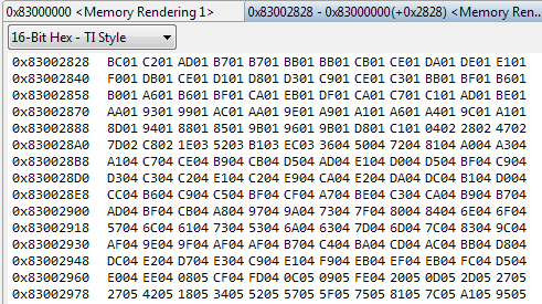
    But one think is wrong. The 16 bit pixels are stored in big endian format. Why? I can't find options to configure a little endian output.

    To modify some platform options, like the memory size and I2C control, I integrated the whole driver sources of the HDVPSS into the CCS 5.4 project to compile it.

    I have the following options enabled:
    TI_814X_BUILD
    PLATFORM_EVM_SI
    PROFILE
    CUSTOM_MEM_FRAME_HEAP_SIZE=16
    VPS_CPAT_ERR_TIME_TRACK_ENABLE
    VPS_CPAT_FID_RPT_TIME_TRACK_ENABLE
    CAPTURE_APP_DEBUG_LOG
    VPS_CAPTURE_RT_DEBUG


    Regards,

    Milan

  • Hi,

    Answers inline,

    Milan said:
    I am confused about the HDVPSS capture configuration:.
    createArgs->videoCaptureMode = VPS_CAPT_VIDEO_CAPTURE_MODE_SINGLE_CH_NON_MUX_DISCRETE_SYNC_HSYNC_VSYNC;
    createArgs->videoIfMode = VPS_CAPT_VIDEO_IF_MODE_16BIT;
    createArgs->inDataFormat = FVID2_DF_YUV422P;
    The VIN parser expect YUV422 frames, but the sensor has a 12 bit RGB format. How it works? Is it a workaround, because there is no raw input format supported from the HDVPSS driver?

    If you have 12-bit, you can connect 12-bits to VIP input port and say that input format is YUV and output format is YUV, so no conversion will occur. Remaining 4 bits either you can ground or you can tie it to VDD. Your 12-bit will be received in memory in a 16-bit container with 4 LSb or MSb bit being always low or high based on how have you tied those 4 not used bits. If your sensor gives Hsync and Vsync out you can just configure it for Hsync and Vsync mode.

    Milan said:
    createArgs->inScanFormat = FVID2_SF_INTERLACED;
    Here the same. The sensor produces progressive frames.

    You have to make it progressive since your sensor is progressive.

    Milan said:
    pOutInfo->dataFormat = FVID2_DF_YUV422I_YUYV;
    This is an output format for further processing. The demo converts the frames from Bayer to YUV. It is not understandable.

    If you make input format as FVID2_DF_YUV422P and output format as FVID2_DF_YUV422I_YUYV no conversion happend inside VIP. So if you feed 12-bit RAW you will get 12-bit RAW in 16-bit container where 4 MSbs or 4 LSbs will be either 0 or 1 depending on how have you connected the remaining 4-bits.

    Milan said:

    I am happy, that I get a monochrome frame with only one generated plane in the memory from the FVID2 object (I don't have display functionality).
    But one think is wrong. The 16 bit pixels are stored in big endian format. Why? I can't find options to configure a little endian output.

    To modify some platform options, like the memory size and I2C control, I integrated the whole driver sources of the HDVPSS into the CCS 5.4 project to compile it.

    Better is you compile using command line. If you have HDVPSS package you can go through userguide to see how to compile using command line. I dont think you need to change any options for compiling you may have to modify sample application in one way or other to suit your hardware.

  • Hello Hardik,

    Thanks for your inputs.

    I am happy, that I get a monochrome frame with only one generated plane in the memory from the FVID2 object (I don't have display functionality).
    But one think is wrong. The 16 bit pixels are stored in big endian format. Why? I can't find options to configure a little endian output.

    Do you have a solution for the big endian problem? I expect and need little endian. The 4 MSbs of the databus at the VIN are connected to the GND.

    This is a part of the captured image:

    Thanks,

    Milan

  • I think instead of FVID2_DF_YUV422I_YUYV, you will have to use FVID2_DF_YUV422I_UYVY pixel format. This should solve your problem in byte swap. This requires some driver changes as this format is not supported. Also some earlier version of the platform does not support this format. Could you tell me platform and its version that you are using? Also which hdvpss release you are using?


    Regards,

    Brijesh Jadav

  • Hi Brijesh,

    thank you for your input.

    I am using the HDVPSS driver 01_00_01_42 from the av_bios_sdk v00_08_00_00.

    The custom platform is:

    • DM8148 SILICON REVISION 3.0
    • 128 MB DDR2
    • disabled I2C control of the image sensor, because it is controlled from another processor
    • currently disabled MMU an cache

    The output from the modified HDVPSS demo is:

    CAPTUREAPP: HDVPSS Drivers Version: HDVPSS_01_00_01_42
    *** VPDMA Firmware Loading... ***
    VPDMA Firmware Address = 0x85b77dc0
    VPDMA Load Address     = 0x4810d004
    VPDMA Firmware Version = 0x4d0001ad
    VPDMA List Busy Status = 0x00000000
    *** VPDMA Firmware Load Success ***

     636: System Drv Create >>>
     3819: System Drv Create <<<
     3826: Vps_deviceI2cInit >>>
     PLATFORM: [TI814x EVM] !!! --> ignore it
     PLATFORM: CPU Revision [ES2.1] !!! --> ignore it
     PLATFORM: Detected [UNKNOWN] Board !!! --> ignore it
     PLATFORM: Base Board Revision [REV A] !!! --> ignore it
     PLATFORM: Daughter Card Revision [REV A] !!! --> ignore it
     CAPTUREAPP: CaptureApp_init() - DONE !!!
     CAPTUREAPP: HANDLES 1: MODE 0000 : CH 1: RUN COUNT 10: OUTPUT:12289:12292 !!!
     VIP 0 RES: DRV [fvid2_vps_capt_vip_ti, 0x0dca0000] path alloc in progress ...
     VIP 0 RES: [PORT_A    ] is allocated in EXCLUSIVE mode
     VIP 0 RES: [PORT_B    ] is allocated in EXCLUSIVE mode
     VIP 0 RES: [Y_LOW     ] is allocated in EXCLUSIVE mode
     VIP 0 RES: DRV [fvid2_vps_capt_vip_ti, 0x0dca0000] path alloc is DONE !!!
     VIP 0 MUX: MULTI CH = 1
     VIP 0 MUX: RGB LO   = 0
     CAPTUREAPP: 0: CaptureApp_create() - DONE !!!
     CAPTUREAPP: Starting capture ... !!!
     CAPTUREAPP: Starting capture ... DONE !!!
     CAPTUREAPP: Capture in progress ... DO NOT HALT !!!


    Thanks,

    Milan

  • Hi Milan,


    I checked in hdvpss latest release, but this format is not supported. Someone in the forum has already added the code and made it workin. Could you please try this changes? You can get the changes from the below link.


    http://e2e.ti.com/support/dsp/davinci_digital_media_processors/f/716/p/223726/793730.aspx#793730


    Regards,

    Brijesh

  • Hi Brijesh,

    thank you.

    The modifications of Tim Tan solved the big endian issue. Now the captured output is little endian and correct. Great!

    Each FVID2_frame Object has one of three valid frame pointer, which is also correct for monochrome capture.

    I would like to understand the dependencies and the coherence of the YUV initialization to capture a monochrome source. Hardik Shah wrote that the monochrome capture is possible in 16bit mode. Is it possible to use the 8-bit mode for monochrome caturing? Can I find these information in the "TMS320DM814x High-Definition Video Processing Subsystem (HDVPSS) - User's Guide" or in the HDVPSS-Driver Guide?

    Thanks,

    Milan

  • Hi Milan,


    VIP does not support monochrome data capture natively. what we did is we captured this data as if it is YUV422 data. We could also capture data in 8bit mode and treat it as YUV422 data. it will be stored as UYVY format. It supports both in embedded and discrete sync format. See this is ok for you.


    Regards,

    Brijesh Jadav


    Rgds,

    Brijesh