This thread has been locked.

If you have a related question, please click the "Ask a related question" button in the top right corner. The newly created question will be automatically linked to this question.

DP83822H: Reset on negotiation

Part Number: DP83822H

I am still having the same problem I was having before.  The part does not actually seem to physically reset (all clocks appear to be continuous) but the connection drops and then begins negotiation again.  f I read the set-up registers everything appears to be configured correctly.  Attached is a schematic of the relevant part of the circuit.  Some of the nodes are not labelled correctly for this part because the have alternate uses for different configurations of the circuit.  This happens if the part is connected to my micro or separate.DP83822 schematic.pdf

  • Hi Joseph,

    Are you trying hardware reset via Reset pin or via software? If its hardware reset, does the reset pulse meet the datasheet requirement?
    Can you try writing 1 to bit 11 in register 0x00 to put the PHY in power down and then initiating hardware reset? If the PHY comes out of power down mode and gets in to normal operation then reset is working correctly.
    In your schematic I did not see any capacitors on the crystal near pin 23 and 22. Are they included on a separate page?

    -Regards,
    Aniruddha
  • I am not trying to do a reset. Rather right after a link between the PHY and the Ethernet switch is formed it is immediately (~ 1 sec) dropped. I don't think it is really a reset. I can reset the device by bringing the hardware pin low or writing to the register but this doesn't change anything.

    The crystal has load capacitors built in (ECS-250-20-33-DU-TR). I put this same crystal on the demo board and removed the load capacitors and it seems to work fine there.
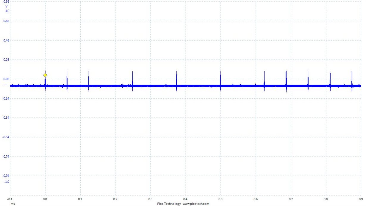
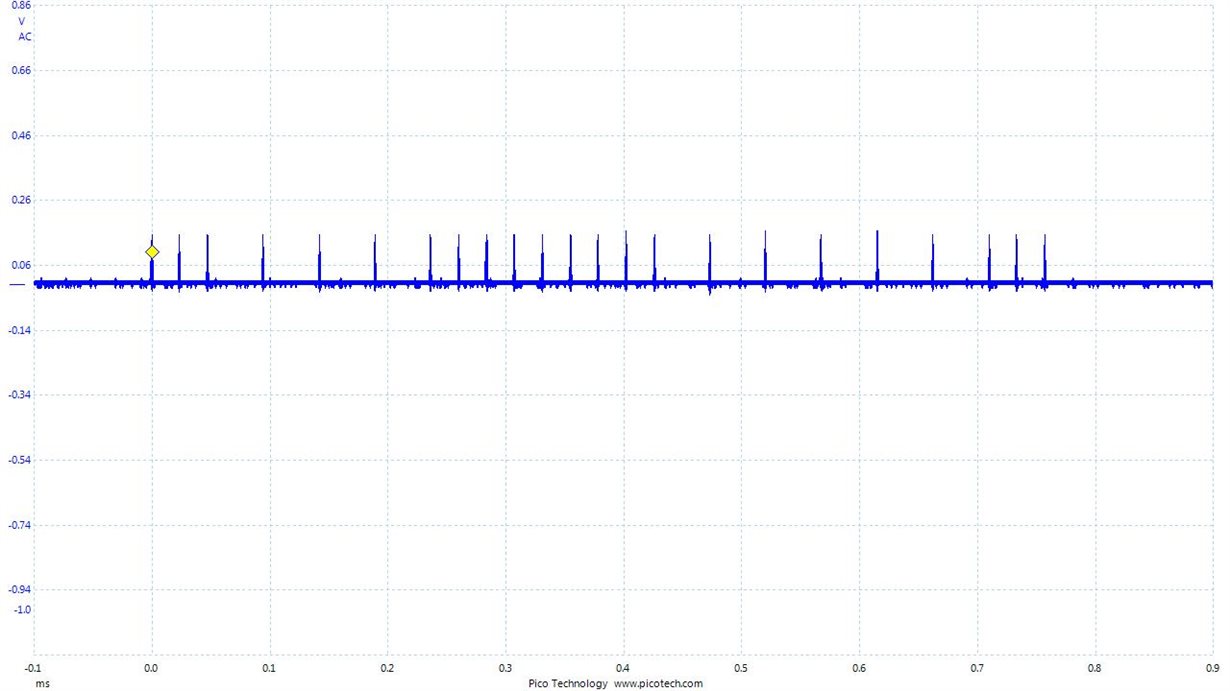
  • The rate of link pulses appear to be different between my board and the demo board as well.  The ones on my board seem to be more often although the pulse shapes are similar.  Not sure if this is a clue to what might be going on.

    Demo board

    My board

  • Hi Joseph,

    Can you read register 0x17, 0x467 and 0x468 for us please?

    In the schematic I do not see pull-up or pull-down resistors on LED_0 and LED_1. 

    A pull resistor is required on LED_1, please see the datasheet.

    From the image, you are most likely bootstrapping into the 50MHz operating mode.

    Register 0x17 will let us know if this is the case.

  • That was my original thought as well but it doesn't appear to be the case from the registers. For some reason bit 6 is set in register 0x17 but not bit 7. Below is all of the relevant registers.

    00 0x00003100 (Hex)
    01 0x00007849 (Hex)
    02 0x00002000 (Hex)
    03 0x0000A240 (Hex)
    04 0x000001E1 (Hex)
    05 0x00000000 (Hex)
    06 0x00000004 (Hex)
    07 0x00002001 (Hex)
    08 0x00000000 (Hex)
    09 0x00000000 (Hex)
    0A 0x00000100 (Hex)
    0B 0x00001000 (Hex)
    0C 0x00000000 (Hex)
    0D 0x00000000 (Hex)
    0E 0x00000000 (Hex)
    0F 0x00000000 (Hex)
    10 0x00000002 (Hex)
    11 0x00000108 (Hex)
    12 0x00000000 (Hex)
    13 0x00000000 (Hex)
    14 0x00000000 (Hex)
    15 0x00000000 (Hex)
    16 0x00000100 (Hex)
    17 0x00000041 (Hex)
    18 0x00000400 (Hex)
    19 0x00008021 (Hex)
    1A 0x00000000 (Hex)
    1B 0x0000007D (Hex)
    1C 0x000005EE (Hex)
    1D 0x00000000 (Hex)
    1E 0x00000102 (Hex)
    1F 0x00000000 (Hex)
    467 0x00002001 (Hex)
    468 0x00000000 (Hex)
  • Hi Joseph,

    For register 0x467 and 0x468 you need to use extended register access.
    Please follow these steps to read those registers:

    write 0x1F to register 0xD
    write 0x467 to register 0xE
    write 0x401F to register 0xD
    read register 0xE (value in 0xE is the value that is in register 0x467).
    Repeat for 0x468
  • I did not realize that.  Now both registers read as their default values:

    0x467 - 0x0FC3

    0x468 - 0x0000

  • Hi Joseph,

    Thank you for the register dump.
    Like you mentioned, the bootstraps are correct.
    This still looks like a clock related issue. Have you probed XI with a low pF probe to see what the frequency is?
    What is the part number of the crystal?

    It also looks like you are missing the 3.3V connection on the 49.9 ohm termination resistors.
    Those resistors must be pulled up to 3.3V like the CT pin of the transformer.
  • Ross,

    Yes I have probed the clock and it is definitely running at 25 MHz. The crystal is an ECS-250-20-33-DU-TR. As I mentioned replaced the crystal on the demo board with this one and it worked fine.

    The board does not have 3.3V connections on the 49.9 ohm resistors but I added the connection and it did not change anything.

    Thanks,

    Joe
  • Hi Joe,

    It looks like your system has a link drop issue and not a reset issue. Does your System keep transitioning between link up and link down?

    From your post above, you made some changes to add pull up on the 49.9ohm resistors. Can you confirm that the Line driver termination circuit matches the datasheet requirement in Figure 33 TPI Network Circuit?

    After the circuit is changed to matched the datasheet recommendation, try it with the ethernet switch and with any other known good 10/100 PHY if you can.

    Lastly, I found the datasheet for the crystal that you mentioned (www.ecsxtal.com/.../ecx-32.pdf) and it doesn't say anything about integrated loading capacitors. Please correct me if I am looking at the wrong document.

    -Regards,
    Aniruddha
  • Aniruddha,

    Yes, the link drops as you say it is not resetting.

    The circuit is now the same as in Figure 33 on the data sheet.

    I have tried connecting it to several different switches and directly to my computer and get the same interment connection on all of them.

    The 20 in the part number is the load capacitance. If you look towards the bottom of the datasheet in the part number section you can see it.

    Thanks,

    Joe
  • Hi Joe,

    The load capacitance in the crystal datasheet is the optium value that crystal needs for proper operation. We have TI App note (http://www.ti.com/lit/an/swra372c/swra372c.pdf ) on crystal selection and calculating the loading capacitors. Generally the capacitor value is selected to be a little less than twice the load capacitance specified in the crystal datasheet. Since the load cap is 20pF, I would recommend putting 33pF cap to ground on each terminal of crystal. Could you try this and test again?

    -Regards,
    Aniruddha