This thread has been locked.

If you have a related question, please click the "Ask a related question" button in the top right corner. The newly created question will be automatically linked to this question.

DS90UB954-Q1EVM: I2C Communication stops when J16 VDDIO set to VDD3V3 3.3V

Part Number: DS90UB954-Q1EVM
Other Parts Discussed in Thread: ALP, USB2ANY, TCA9406

Hello,

I have a DS90UB954-Q1EVM board communicating with a 953 serializer in a camera, connected through a Fakra connector to J29.  The device is locked.

The DS90UB954-Q1EVM board appears to stop communicating with ALPS when the J16 VDDIO voltage select jumper is set to VDD3V3 3.3V.

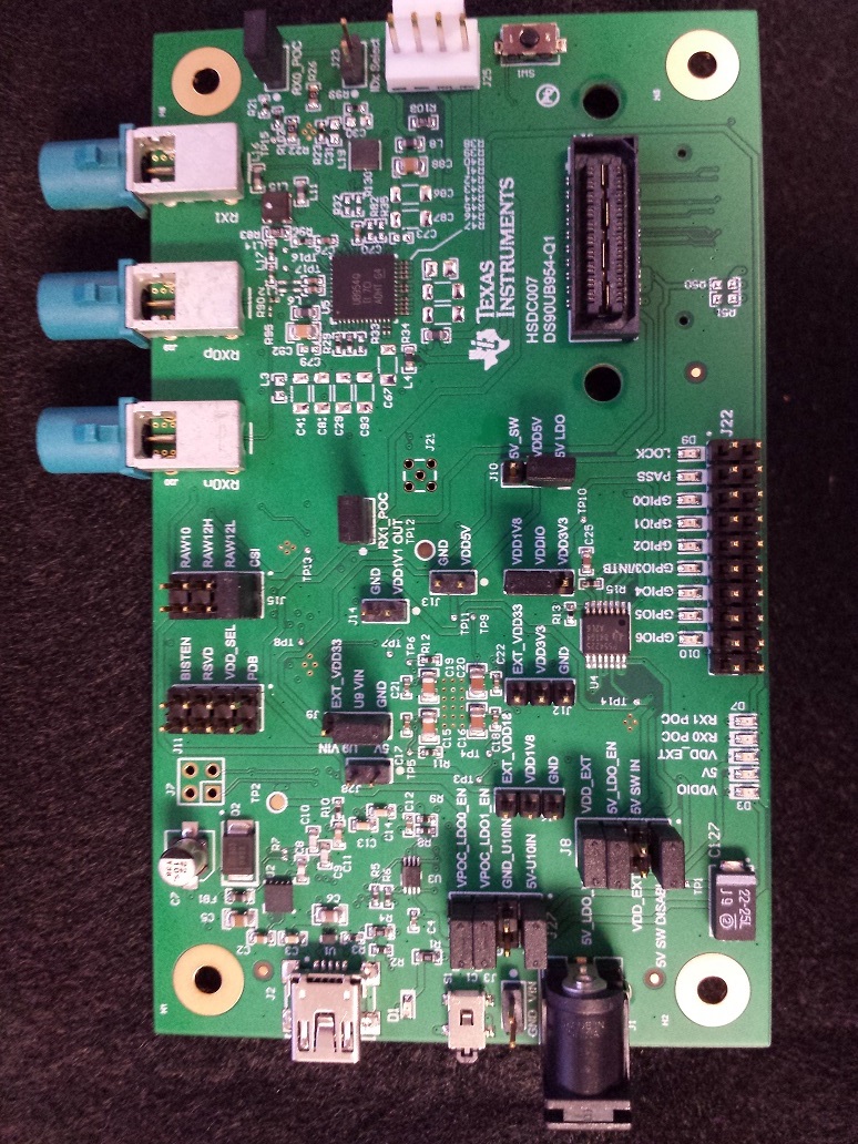
The user guide indicates Pin 1-2 are shorted together to use 3.3V as the default, but my device was received with pins 2-3 connected, to use 1.8V.

At 1.8V, ALPS correctly identifies the connected serializer as a 953 and locked.  If the jumper is moved, the app hangs until the 1.8vio is restored.

If the app is started with the jumper set to 3.3V, it identifies the serializer as 913, and not locked, despite the lock LED D9 glowing.

I would like to use J25 to connect to I2c using 3.3V instead of 1.8V.   Other EVMs work at 3.3V i2c.

J25 is not currently connected to any external device.

I have consulted hsdc007_reva_evm.pdf for the updated schematic with the wiring of I2C connector J25 (opposite of Table 6) and J16.

Thank you,

J

  • Hello J,

    Could you please confirm the version of ALP you are using? Just want to be sure you are using the latest version. Also, could you make sure you have downloaded the latest ALP-PROFILE-UPDATE and applied it. TI releases ALP profile updates with new features and bug fixes. You can test if you have the latest profile update installed by checking Help--> About this program.

    I think all the board jumper settings might have to be checked. Could you please upload a photo of the board jumper and switch settings?

    Thanks,

    Vishy

  • Hello, Vishy.

    The ALPS version is 1.057.0010 the latest version available this week, with the updates.

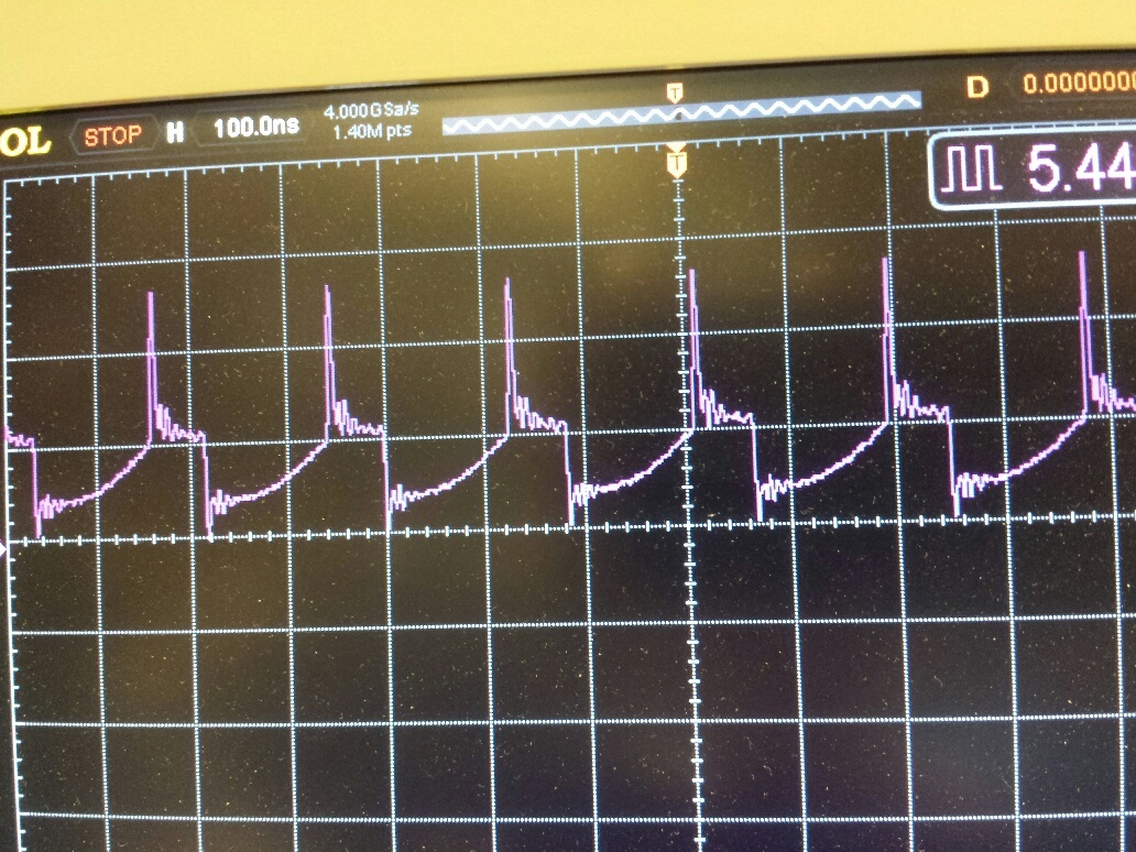
    I have scoped the i2c pins and what is happening is that when my camera is attached it attempts to function for 2 i2c word transmissions, at 3.3v Then the scl becomes corrupted, as if there is a voltage limiting component, and goes to a constant high frequency 5.5mhz 0~2.5v corrupted scl trying to clear the bus.  SDA stays high at 3.3v. If the camera is then disconnected the 5.5mhz scl remains.  The only thing that stops the 5.5mhz scl is removing the vddio jumper J16.  Scl does not get corrupted if the camera is not attached... but that situation is not useful.  I have also tried a different camera that functions with the 934evm, and it also has the same results.

    The Scope displays the corrupted scl at 1v,100ns/div.

    Thanks,

    J

  • Hello J,

    Thanks for the picture and the screen shots. Let me experiment on Monday and get back to you.

    Thanks,

    Vishy

  • Hello J,

    >>> The user guide indicates Pin 1-2 are shorted together to use 3.3V as the default, but my device was received with pins 2-3 connected, to use 1.8V. At 1.8V, ALPS correctly identifies the connected serializer as a 953 and locked.  If the jumper is moved, the app hangs until the 1.8vio is restored. If the app is started with the jumper set to 3.3V, it identifies the serializer as 913, and not locked, despite the lock LED D9 glowing.

    I got a 954EVM + 953EVM setup with J16 jumper selected to 3.3V. See picture below. 

    With the above seup, I can get ALP to connect and able to examine remote 953 registers. See screen shot below

    Could you show me a picture of your complete setup? I think there may be some other issue causing your problem.

    I also looked at the latest user guide. Figure 4 shows J16 default as 1.8V but in table 7 default is shown as 3.3V. Since section 3.1 says "VDDIO is set to 1.8V", I think table 7 showing 3.3V as default is error. Thanks for pointing this out.

    Thanks,

    Vishy

  • Hello J,

    >>>I have scoped the i2c pins and what is happening is that when my camera is attached it attempts to function for 2 i2c word transmissions, at 3.3v Then the scl becomes corrupted, as if there is a voltage limiting component, and goes to a constant high frequency 5.5mhz 0~2.5v corrupted scl trying to clear the bus. 

    Please give us more information on your setup. Is your setup 954EVM + 953EVM + Image Sensor? What sensor are you using?  Are you using ALP to initialize the sensor or some SOC? How is 953 + image sensor powered?

    Thanks,

    Vishy

  • The setup is a 954EVM + 953 serializer integrated into a camera, or a 933 serializer integrated into a camera, and connected and powered by 9v over a coax Fakra cable.  The sensor is not initialized.  The i2c is polled by ALPS through the usb2any.  If the VddIO is raised above 2.7v ( limit discovered experimentally), the i2c bus produces the 5.5MHz clock.

  • Hello J,

    >>>The setup is a 954EVM + 953 serializer integrated into a camera, or a 933 serializer integrated into a camera, and connected and powered by 9v over a coax Fakra cable. 

    Thanks. The USB2ANY I2C communication is initialized for 400kHz .  I am not sure why you are seeing 5.5MHz.

    Did you check the serializer ID register in 954 (0x5B) gets initialized properly when you connect your 953 serializer + camera board? Did you confirm 954 and 953 are locked. I assume serializer + camer is a custom board and not our 953EVM.   Is this a module from third party? Give us any information you can. Please share a screenshot of the ALP info tab when 954EVM is connected to your board. 

    Besides ser_id and ser_alias_id register, you also have to initialize slaveid and slave alias to access the sensor. Please share any initialization code you load as well. There are some example initialization scripts as part of Predef scripts folder under ALP installation.

    Thanks,

    Vishy

  • Vishy,

    1. I was waiting to setup the registers until I can connect with my automated external i2c cpu, running at 3.3V.

    2. How does lack of proper register setup cause the i2c hardware to go crazy at 2.7v and higher ?

    3. How would I setup those registers, if the ALPS environment locks up at 3.3V ? Switch the jumper after ? And what if my camera gets disconnected and loses power to its deserializer ?

    4. I think I have an EVM with a hidden defect, AND I am notifying TI of it in this statement, since I have not seen any reasonable explanation for the change in operation between 1.8v and 3.3v vddio. Do you know the procedure for replacing it ?  You are a member and not an employee, correct ?

    Thanks, J

  • Hello J,

    I am trying to reproduce the 3.3V issue you point out in our setup so we can debug this.

    In the 954EVM + 953EVM setup, we can always see a valid lock between 954 and 953 whether J16 selects 1.8V or 3.3V. Note 954 and 953 have to be locked for valid communication then in ALP info tab we see 954 Port 0 status as linked to 953. Also, when 954 and 953 are locked, register 0x5B (serializer id) of 954 gets automatically loaded with the locked serializer address. That's the reason I was asking you to check 0x5B register.

    Do you see a valid locked status when you pair 954EVM with your serializer + imager board? Please connect ALP to 954EVM USB and upload a capture of the ALP info tab for both 1.8V and 3.3V setting of J16. That might give us some reason for the issue.

    Thanks,

    Vishy

    .

  • In my very first post I state that ALPS sees the lock status and serializer type as 953 at 1.8V.

  • Hello,

    I setup and tested 954EVM with a LI 953 Imager Module. See photo of the setup below and ALP connection screen shot. With J16 selecting 3.3V VDDIO and the imager module POC powered I am not able to reproduce your issue. ALP is able to connect and access the device.

    Thanks,

    Vishy

  • Hello J Guy,

    Reading through this thread I was a little bit confused - in this testing are you connecting to the USB mini port on the EVM? Or are you connecting to the J25 header with an external USB2ANY?

    Thanks,

    Casey 

  • From my first post:

    "I would like to use J25 to connect to I2c using 3.3V instead of 1.8V.   Other EVMs work at 3.3V i2c.

    J25 is not currently connected to any external device."

  • Yes, but I;m trying to double confirm you are using the mini USB port correct? Nowhere in this thread was it explicitly stated that you were connecting to the mini USB port. We also have not received a picture of your full setup. 

    Thanks,

    Casey 

  • Here it is triple confirmed - the pcb is connected as-is, out of the box, using the normal mini-usb to connect USB2ANY to ALP.  ALP functions normally until the vddio is set to 3.3v, and my integrated camera containing a 953 serializer is attached.  When this camera is attached, it first locks (at 1.8vddio), and ALP behaves normally indicating the correct serializer type, address, and lock status.  At vddio 3.3v, the i2c goes into 5.5mhz scl bus reset and never recovers, making any register changes impossible.  I do not have a leopoard camera yet, but will be trying one soon.

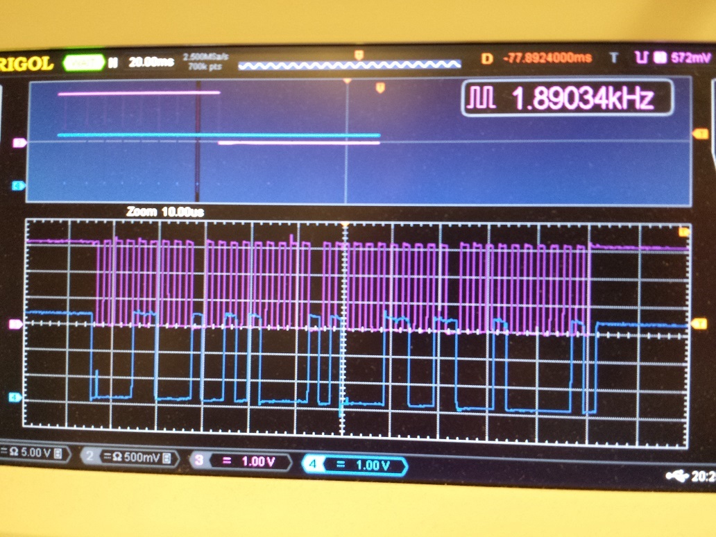
  • This is the last succesful i2c transfer

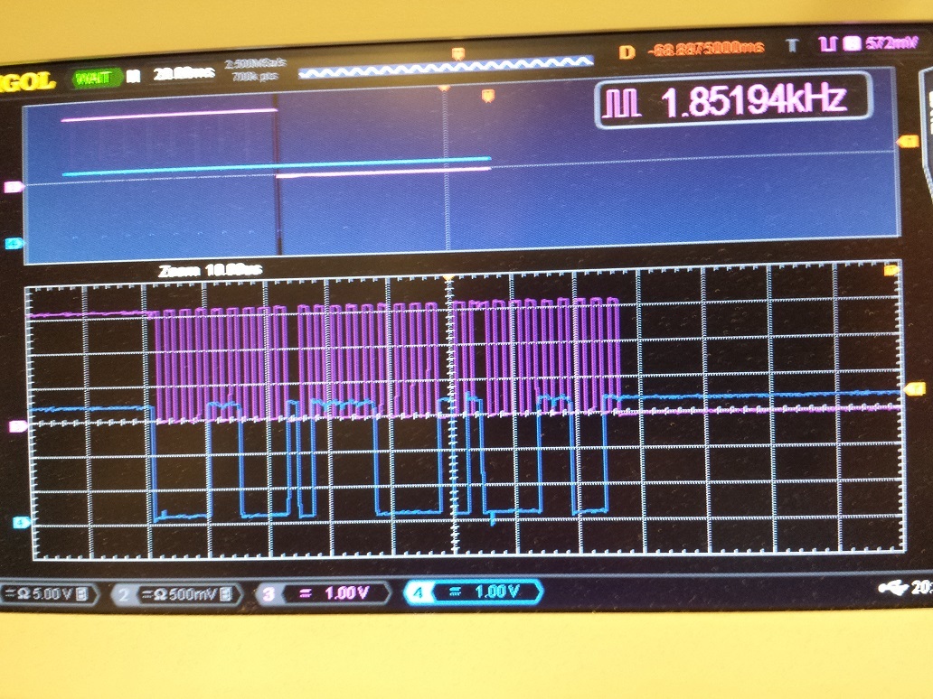
  • This transfer is incomplete - the clock stays low. After several (5?) ms of the scl low and sda high, the 5.5MHz scl clock starts.

  • Hello J Guy,

    We can't seem to replicate this issue on our hardware. Were you able to test with the Leopard module? If so and you are still seeing this issue I will check if we can do a replacement on your EVM. 

    Best Regards,

    Casey 

  • Update:

    1.  The problem does not occur with the Leopard camera.

    2. The I2c timeout does occur with my camera, at 1.8v VDDIO, but the system does recover.  I cannot capture the recovery on the scope at this time.

    The general problem: If an i2c timeout occurs, AND the VDDIO is set to 2.7v or above, the SCL produces a disabling 5.5MHz signal.

    If the TCA9406 I2c bus voltage translator is disabled and bypassed, the VDDIO can be set to 3.3V, without the disabling 5.5MHZ signal occurring on SCL.

    I think the problem occurs because of the use of the TCA9406 at the same voltage on both sides of the bus.

  • Hello J Guy,

    Ok thank you for pointing out this issue with the TCA9406 configuration. We will keep it in mind for our future designs. 

    Best Regards,

    Casey