This thread has been locked.

If you have a related question, please click the "Ask a related question" button in the top right corner. The newly created question will be automatically linked to this question.

DS26LS31MQML: DS26LS31MJ

Part Number: DS26LS31MQML

Dear Sir,


  Please find the below block diagram. There are two systems named as SYS1 and SYS2 connecting through RS422.


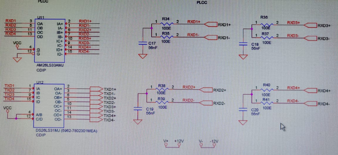
SYS1 is designed by us.  We are using DS26LS31MJ-SMD or DS26LS31MJ/883 as QUAD RS-422 driver. ( SYS2 is developed by another company)

On Testing, we found the TX+,TX- pin of the port connected to SYS2 alone ios getting damaged repeatedly. Other ports of this driver are working fine.

As we had AM26LS31MJB also in our stock, we tried replacing  DS26LS31MJ  by AM26LS31MJB. We have not faced any issue in communication and the systems are functioning satisfactorily.  From the datasheet, we are not finding any difference between DS26LS31MJ and AM26LS31MJB.

 Kindly get back to us for the probable cause of failure. Expecting reply as early as possible as we have assembled many systems with DS26LS31MJ.


Thanks & RegardsTI query.docx

Alok Ranjan

  • Alok,

    The transmitter should not be damaged from driving a receiver.   Possibly exposed to electrical overstress.  ESD or ground issue?

    Can you provide the schematic?

    Do SYS1 and SYS2 share common ground?  (through cable?)

    As part of testing does sys1 and sys2 get disconnected/reconnected? (possible ESD exposure?)

    What are other channels that are not failing connected to?  Cabled as well? 

    What does output look like after failure?

    Regards,

    Wade

  • Hi,

     Please find the schematics in the attached file.

    Yes, SYS1 and SYS2 sharing common ground through cable.

    No, As part of testing sys1 and sys2 not getting disconnected/reconnected.

    Channel 1 and Channel 3 is connected to some other system through separate cable and working satisfactory, Channel 3 is Unused.

    The output of the driver is High while input is ok.

    Regards

    Alok

  • Very strange.

    Do you have scope shots of data on a working channel that gets damaged, and one of the other working channels?

    What is temperature of device when operating?  Has this been measured?

    Is your cable 100ohm impedance to match your termination?

    Thanks,

    Wade

  • Dear Sir,

    The systems are operated at room temperature. UNITS ARE TESTED IN CUSTOMER LABORATORY.

    We have delivered the unit after checking the port with loopback only.

    As the units are at customer place we will try to get the waveforms.

    But remember the waveform ( data) toggling at all inputs of the driver and output on working channels were toggling  and in failed channel is high.

    As the failure was repeating, we have put the IC base and replaced with new IC. The observation is some times initially one or two times communication was SUCESSFUL with system 2 and then failure observed. In some cases initially only communication failure observed. When tested in all failed units TX+ , TX- were not toggling when input is fine. All these were observed with DS26LS31MJ

    Accidentally, we saw three numbers of  ICs AM26LS31MJ in our stock and we tried with them and all are working satisfactorily. As we can't replaced in many  units already supplied we want to find out root cause of the same. The same cable is used in both cases . There is 120 ohm termination at the receiver end (SYS2)

    Kindly get back as soon as possible. Is there any difference between DS and Am chips?

    Regards,

    Alok ranjan

  • Alok,

    I would like to see the input to the RX on scope shots.  It would also be good to capture multiple, with an eye diagram type of capture.  Possibly set trigger on a larger voltage as well, to possibly see if any spikes are seen.

    There is something that is causing stress on the RX, and thus we are estimating that it is damaging the input. 

    Do you know the source IC and schematic from the TX that is causing issue?

    Possibly there are spikes or other anomalies that the RX is seeing?

    What is duration that devices work before they fail?  Do all units fail on this channel after some duration?''

    The two device are uniquely designed, as one originated from National.  However, they function equivalently with similar specifications.

    Regards,

    Wade

  • Dear Sir,

    I think there is a communication gap. It is TX+ and TX- is getting damaged ( As this chip is QUAD driver and not receiver)

    Most chip  fail immediately , some after few operations ( say for few minutes)

    regards,

    Alok ranjan

  • Yes, I apologize.

    I misspoke.  Understood. 

    Please still capture scope shot.   It may provide insight into potential issues.

    If possible, can one of the other channels be connected to SYS2 to see if it causes failure on different channel?

    It does not make sense that TX can be damaged this way.  

    Can you confirm voltage on the enable signals?

    Per schematic, they are VCC 5V.

    I am OOO most of today, and Monday.

    Regards,

    Wade

  • Dear Sir,

    We have discussed with our customer. They can't connect other channel to SYS2.

    Also the Tx+ and TX- can't be monitored with SYS2 connected as it is not accessible. When there is a failure the card in which quad driver is there is removed and tested in card level test rig only.

    C/D and A/B pins are at +5V level

    regards,

    Alok Ranjan

  • Alok,

    I have a few more questions that may help determine the cause.

    1) Can you probe the outputs while connected to the load?  I believe you indicated no.  If not, can you probe with a separate load?  We would like to see if the driver output is degraded, or not functioning at all.

    2) Can you provide scope shot of the input to the driver?   It could be possible that this input is getting EOS damage and that is reason why that channel is failing.  Does this channel share same driver source as the other working channels?  What is source?

    3) If you have a removed device, is it possible to curve trace differential outputs and compare to working outputs?   This will give good indication if the transmitter is damaged.   This could also be done with the input as well.

    Regards,

    Wade

  • Alok,

    Any update to your testing?  

    I'm going to close this post.  If you have new information, please post back and it will re-open.

    Regards,

    Wade