This thread has been locked.

If you have a related question, please click the "Ask a related question" button in the top right corner. The newly created question will be automatically linked to this question.

CCS/TM4C1294NCPDT: Unable to Program some custom boards

Part Number: TM4C1294NCPDT
Other Parts Discussed in Thread: UNIFLASH, SEGGER

Tool/software: Code Composer Studio

I have 50 boards with the TM4C1294NCPDT uP, running at 24MHz. On 10 boards the JTAG will not work, with same setup, if I plug the JTAG into a "good" board, same setup, same hardware, same session, it programs just fine. We did not put in the RBIAS resistor on any of the boards, again 40 will connect and program through the JTAG.

I am about to fab a production qty and have to get this resolved. 

RBIAS and JTAG post:

e2e.ti.com/.../587050

I use either the Launchpad eval board or the XDS100v2, both work fine and multiple times on good boards. I have tried Uniflash and LMFlash, both work. I took 2 boards, put in RBIAS and I still get the same error. I tried and finished Unlock; still dead.

If an attempt to program the uP w/o RBIAS, is it fried?

Output from Uniflash:

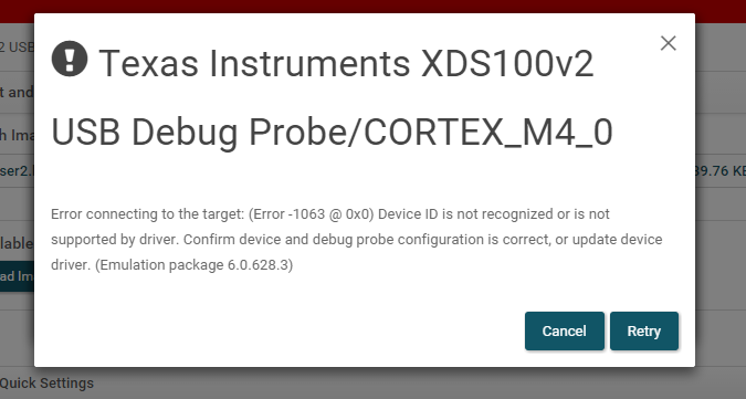
  • TM4C1294NCPDT: JTAG Error, error connecting to the target
  • Without the RBIAS resistor on the board, you will have problems connecting with JTAG. The boards that you were able to connect to, may have issues connecting in the future. The boards you have not been able to connect to are not damaged. Add an RBIAS resistor and you should be able to connect and program the flash on those boards. I strongly suggest adding the RBIAS resistor to all of your boards. A 4.7KOhm 10% tolerance resistor can be used in place of 4.87K Ohm 1% tolerance resistor if the Ethernet is not used.
  • Bob,
    Thanks for the reply.
    But, from above: "I took 2 boards, put in RBIAS and I still get the same error. I tried and finished Unlock; still dead."
    I am using an HCMOS 15 pF 24MHz osc.
    If the osc is the problem, at what f does the JTAG issue go away, not that my design allows that but just to verify the problem.
  • While your (Add the bias R is the "party line") - poster noted that he "tried just that" - upon 2 DOA boards - and got nowhere!
    He wrote, "I took 2 boards, put in RBIAS and I still get the same error."

    Such a pity that "Valued Vendor Resource" is called - again & again - to "Failed JTAG" - which has LONG been known - yet there IS time/effort to harpoon "LIKE!"     Might "Misuse of Valued Resource" enter the realm?

  • Jesse,
    My apologies. I clearly did not read your post carefully.

    I am wondering if the use of 24MHz is close enough to 25MHz to cause the boot loader to try initializing the Ethernet, yet far enough away to cause an issue. If possible, can you replace the 24MHz oscillator with 25MHz on one of the boards that you added the RBIAS resistor? Just as a test to see if this is related to the ROM boot loader.
  • A second thought, you might try just removing the 25MHz Oscillator and trying JTAG. The device will run off of the 16MHz PIOSC. If this works, it would verify that the JTAG connections are working correctly.
  • JESSE MEISTERLING said:
    I have 50 boards with the TM4C1294NCPDT uP, running at 24MHz.     On 10 boards the JTAG will not work, with same setup, if I plug the JTAG into a "good" board, same setup, same hardware, same session, it programs just fine.

    Thus it is suggested - yet not certain - that those 40 boards "Not Failing" do work!

    Should that be the case - would it not prove useful to, "Swap the key frequency determining components" - from "Good Boards" to "Failed Boards" to attempt to "tease out" the Failure's Source?       (i.e. external components vs. MCUs)        It is important that the MCU's Reset Circuit be checked as well - prior to such component swap.

    As a "painful & last resort" - you may, "Replace a failed board's MCU w/a new one" (not swapped) - leaving everything else on the failed board -  "exactly the same."      

    These 2 methods have long proven their value to, "Speed, Ease & Enhance" Failure recognition & identification...    

    It is wise always to review "date codes" (to learn if the failures  - or successes "cluster") - and also "Review & insure that all ESD handling safeguards are, "Up, Known & Strongly Enforced..."

    It would also be helpful if you had (logged), "Where in the programming cycle each failure had occurred?"      (an operator change - or inadvertent setting change - may prove the culprit...)       Fifty such boards - awaiting programming - "eat space" and may have subjected "certain of the boards" to "improper movement & handling!"

  • Of the 50 brds, 2 builds of 25 - 6 months apart, new fab, new parts order for each build.
    3 of the first 25 had the JTAG failure, 7 of the second 25 have the failure.

    My first try was to switch 2 uPs out; NG, then, on those same 2 brds, I put in the RBIAS pull down... NG.
    The remaining 40 brds work great! On the brds that work, each has been re-programmed at least 2-4 times... still work.

    Like I said: if I move the JTAG conn from a "bad" brd into a "good" board, same setup, same hardware, same session, it programs just fine.
    LMFlash just crashes with a "0" code, Uniflash puts up the notice above.

    As far as static, my assembly house is cert'd, I unwrap, store and handle on static matted floor and table, min 50%RH, building similar boards (not TI uP) for 16yrs. I would accept one or two (haven't had one) but 10???

    I am having the OSC replaced with a 24MHz crystal and the RBIAS R put in on 2 more failed brds. FYI, the early proto brds had a crystal so I left those pads on the prod brds. We'll see.
  • Feel your pain - note that the methods suggested have, "Led to solutions" @ multiple clients. (otherwise - what's the point.)
    Agreed that 10/50 (20%!) IS a horror.

    Might you have a friend in the Biz w/access to "Segger's J-Link?"       This proves a vastly superior JTAG/SWD Probe (far more established - more capable/robust - and HAS "restored connections" to boards in a situation similar to yours - MULTIPLE TIMES!)

    We always recommend use of external pull-up Rs - employing MCU's internal (high resistance) Rs invites such issues - never wise...

  • The fact that once the device has been successfully programmed, it can always be reprogrammed is still consistent with this being an issue with the ROM boot loader instead of the JTAG circuit itself. Once there is something programmed at address 0x00000004, the ROM boot loader is not executed. If it were a problem with JTAG signal integrity it would be less consistent from board to board.

    JESSE MEISTERLING said:
    Like I said: if I move the JTAG conn from a "bad" brd into a "good" board, same setup, same hardware, same session, it programs just fine. LMFlash just crashes with a "0" code, Uniflash puts up the notice above.

    By "JTAG conn" do you mean the XDS100V2?

  • Yes, XDS100V2 or LaunchPad programmer, makes no diff.
  • Bob,

    Correct me if I am wrong - but is not "yours" the "first/only" mention of "ROM boot loader?"
  • CB1,
    Yes, I thinks so. Why do you ask?
  • Is the "ROM boot-loader" - even when not specifically "ordered into service" so able to "Disrupt normal JTAG/SWD connection/attachment?"

    If that is so - should not there exist positive means to guard against such undesired/unwanted behavior?

    I saw no mention of "ROM Boot Loader" - instead poster attempts (only) to connect via JTAG!       Thus the "ROM boot loader" - newly added to the scene - deserves question & interest  - does it not?

  • CB1,
    If the device is blank, which I assume the 10 "failing" units are, the ROM boot loader will be executed. As we know from erratum ETH#03 that if you use a 25MHz crystal without RBIAS that it can cause JTAG to not work. In this application, they use a 24MHz oscillator so at first glance we would assume that erratum ETH#03 does not apply. The root cause of erratum ETH#03 is that the ROM boot loader polls UART, SSI, I2C, USB and EMAC for a possible boot load. It checks for 25MHz before checking the EMAC, but its reference to do so is the PIOSC. The PIOSC with a +/- 4.5% tolerance may not be able to accurately distinguish that 24MHz is not 25MHz. Now the next step is speculation on my part, can the ROM boot loader lock out JTAG if it incorrectly detects 24MHz as 25MHz?

    This is why I suggested the experiment to remove the 24MHz oscillator. The ROM boot loader (running off of PIOSC) will not try to initialize the EMAC which may allow JTAG to work. Once some code is programmed into the blank device, the ROM boot loader will not be executed and the part should be able to be reprogrammed even if the 24MHz oscillator is restored.
  • That's a sound explanation - but do recall - under the "identical scenario" 40 boards/MCUs DID Program!

    My firm has programmed beyond 15K "LM3S, LX4F and 4C123" - never/ever desiring nor employing the boot-loader.       Now - were not ALL of those "factory fresh" MCUs blank?      Yet - we "never once" experienced the "horror" suffered upon this poster - thus the "Intrusion of the ROM Boot Loader" appears questionable - does it not?

    In addition - does not the ROM boot loader "require" certain (special) signaling - (i.e. a key GPIO manipulation) before, "Coming into Play."       To "Lock-Out JTAG/SWD" minus such precaution - seems highly suspect - and might that not lead directly to the "Off the Chart incidence of JTAG Lock-Outs" - witnessed here?

    Should there exist "special operation w/in the TM4C129" - of which firm/I have no knowledge (nor interest) - all "bets are off."

    I am doubtful that the ROM Boot Loader is a cause agent - in light of these facts - herein presented...

  • CB1,
    Good points. I think the 10/50 fails might be explained by the imprecision of the PIOSC. If the internal oscillator is on the low side, it might think 24MHz is 25MHz. If it is on the high side, it might correctly assume that it is not 25MHz and skip the EMAC initialization. The test for 25MHz has to have at least a 4.5% margin of error to account for the PIOSC.

    Erratum ETH#03 is unique to the TM4C129 devices with integrated PHY. You would never see this on the TM4C123 devices.
  • Bob,

    Thank you - do note that my motives here are "pure" - it would be "terrific" if some way/how the "incidence of JTAG Lock Outs" could be substantially reduced!      Each time such an event occurs (especially here/now) and vendor experts are present - "some chance for resolution (or at least boosted understanding/connection - arises!")

    May I ask that you return to my post (4:38 PM) above - and examine (newly added) Para 3 - in which I "gravely doubt" ROM Boot Loader as cause agent for this poster's issue...    Such ability to "mask out or dominate JTAG/SWD" - w/out expressly being granted that privilege - seems outside "normal intent!"

    Again thanks your time, effort & attention...

  • CB1,
    I don't question your motives at all. You are asking excellent questions. I don't think it was ever the intent to lockout JTAG. It is an unfortunate side affect of issue ETH#03. I don't know the details of why JTAG is locked out. (I was working on other devices at the time that issue was discovered.) If this issue is related, I will certainly dig deeper to find out. Amit might be able to shed some more light on this issue.

    Jesse,
    Keep in mind that this is just a theory on my part. Let me know if you can do the experiment with removing the oscillator. If that fails to resolve the JTAG connection, we can discard this theory and move on to the next one.
  • Thank you, Bob - and know that I simply wanted to "press hard" for this "long festering issue's" (pardon - yet that's the truth)  "deep dive" - and resulting harnessing & correction.

    If this was me - I'd procure 5 fresh MCUs - and carefully/skillfully "reflow/remove" 2-3 "failed ones" - and "Replace just the MCU!"      And then carefully "attempt to program!"      

    At times - such "brute force methods" serve as BEST/ONLY MEANS to derive instant and powerful insight!       (we seek to discover the problem's location - not yet its cause!)

    We are (still) uncertain of issues "location" - and "nibbling around the edges" won't solve anything - SOON!        Brute Force ... WILL!

  • But, cb1_mobile...
    I had 2 uPs R&R'd, nada...
    Those 2 had the RBIAS mod, nada!
    All work done by assembly house, R&R and RBIAS job look good.
    Carefully? I got 40 working solid on the same bench, same hardware, same time, same me.
    I have rung out the lines w/ the parts on the brd, will have parts sucked off and ring again.
    ???
  • I don't know that we are communicating.       Your issue likely resides:

    • w/in the MCU
    • w/in board's frequency determining and/or reset circuitry
    • if especially unlucky - w/the combination of both

    The "Pull & Replacement" - from a Failed Board - of (only) that board's MCU - and if follow-on testing then proves successful - steers hard toward "MCU as your issue."      May we agree on that?      From years of tech experience - and "gambler's luck" - I'd bet (much) on that outcome as "most likely."      

    It speaks not at all as to "When/where/how the MCU became disabled" - but that's not our area of greatest concern - at this moment.

    As you "appear resistant" to my suggestion - you may also consider, "Swapping the frequency & reset determining components from a "bad board" to a "good one."     Of course our objective is to bring about "Controlled Success or Failure" - via the careful substitution of (either) MCU or support components.

    Your current "method" has left you, "Dead in the water" - has it not?      Bob & I - both being sailors - know that (some) wind IS required ... so too here - so you may escape your "becalmed" state...

  • Bob, cb1,
    Tomorrow my assembly hse will put the crystal on 2 failed brds, replacing the OSC and remove the OSC from another and have the MCU pulled and left off from another.
    We will check them out. I will have the assembly hse x-ray the MCU'less brd.
    I will get a J-Link programmer.
    We will try the J-link on all the brds and especially the 2 brds with the already R&R'd MCUs and installed RBIAS.
    Thank you both for your input into my issue!
  • Thank you - such detail appreciated.

    In the case of "J-Link" insure yours is a valid Segger unit - not an off-shore (illegal) copy.

    In addition - Segger provides detailed software - they have LONG been in the "JTAG/SWD Biz" - their approach (being vendor agnostic) is "far more detailed, tested & expansive" than vendor efforts - here.

    During your use of the J-Link I would "escape" from vendor constrained approach - and employ the J-Link under Segger's software - which has proven ability to "rescue" client-users from conditions (near) identical to those you describe... (Note: neither firm nor myself receive reward for such endorsement...)
  • A quick question:

    A review of 5.2.2.2 in the data sheet says that if there is a failed initialization after a POR the TDO will toggle.

    Is there a pic of this data stream on the JTAG?
    Or am I up the wrong tree?

    Will the J-Link see this?

  • Firm/I have "yet to encounter" a "TDO toggle." That said - we employ ARM MCUs (M0, M3, M4, M7) from multiple vendors - yet have no experience w/your device. (or any w/in the 129 family ... our belief is that is a "one trick pony" MCU (E-Net) which has long ago been passed by other Cortex M4s - surpassing 200MHz SysClock - while providing modern & expansive TFT display drive)

    From my time/reading here - TDO toggle should be easily detected via a scope - I don't know if J-Link and Segger software "looks and/or tests for that." (The Segger forum or a deep dive into the J-Link manual (well over 100 pages - again far beyond any/all limited units offered here) may provide insight...)
  • Well, I'm back with the results of my little R&R experiment.

    First, removing the OSC from the MCU and trying to program with just the JTAG did not work.

    From my engineer:
    Cannot program via JTAG - received error message “Error Connecting to Target” when programming via Code Composer.

    However, removing the 24MHz, 2 ppm OSC:
    support.epson.biz/.../doc_check.php

    and putting in the original prototype 24MHz ±10ppm Crystal:
    support.epson.biz/.../doc_check.php

    worked in both pcbs.

    BTW, the crystal circuit has 2 - 12pf caps tied to OSC0 & OSC1 inputs.
    Everything seems to be in spec (that I can discern).

    Is there an explanation for this?
  • Good for you - glad you persisted - you may note the following:   (direct quote from my post, Thu, Dec 14, 2017 2:31 p.m.

    cb1_mobile said:
    Should that be the case - would it not prove useful to, "Swap the key frequency determining components" - from "Good Boards" to "Failed Boards" - to attempt to "tease out" the Failure's Source?

    In a more recent post I included 3 bullet points in the aid of diagnosis - again directing attention toward the "frequency determining components."        

    Is it not fair & proper - based upon those 2 earlier (and correct) Diagnostic Offerings - that "one or both" receive your "This post resolved my issue?"

    Of interest still - did not 40 of the identical oscillators "perform as desired?"      Is it possible that these 2 failed units were mismarked - and/or did not (effectively) oscillate?

    I would still urge you to acquire a "more proper" programming/debug Probe - saving on "vital tools" rarely (if ever) makes sense...

  • One thing I would do is probe the actual frequency. If you do this I would also suggest attempting to program while your scope probe is attached, it's possible the probe will affect the frequency if you probe at the crystal.

    Also note that different crystals may require different load capacitance.

    Robert
  • Hello, and Happy New Year.

    Short synopsis:

    Built 50 boards with TM4C1294NCPDT and 2ppm 24MHz osc. Provision is on pcb for 10ppm 24MHz crystal. Both OSC and crystal are within the TI doc spec.

    Original 2 builds have no RBias pull down (25 each).

    40 worked fine, 10 have no JTAG port comm to the MCU. We are using both Launchpad and Blackhawk USB100v2 JTAG Emulator.

    Put RBias pull down on 2 of the OSC brds, no diff.

    Pulled OSC (no ext clk) and tried to program thru JTAG, same failure.

    I R&R'd OSC with the crystal. 3 out of 5 work; JTAG programs fine. One of the 3 good brds has no RBias pull down. The 2 crystal failures have no RBias pull down.

    Looks like:

    R&R Osc with crystal has some effect; 3 of 5 have working JTAG.

    RBias makes no diff: 40 OSC and 1 crystal brd w/o RBias pull down work fine.

    I have a comm into the OSC people.

    In total, I built 15 prototype boards with crystals: all worked.

    Built 50 production brds with OSC; all 40 worked.

    Not sure what is going on here. Do you have any suggestions?

  • I do not know what is going on, and am curious. I assume the prototype boards and the production boards are at least slightly different. Can you do a JTAG scan test using the USB100v2? Open the .ccxml file in Code Composer and see if you have a valid "Test Connection" button.

    Running the connection test should give results like this (scroll to the end):

  • Bob,
    Thanks for the reply!
    Having a blizzard now but I will do your tests.
    BTW, the only diff between the proto brd and prod brds are the TI I2C charger and FG chips. and the dual OSC - crystal pads.
    The MCU section and every other peripheral is identical, was originally going to be an alki batt device.
    Spoke to the OSC people, they assure me that the parts are 100% tested and can't imagine a 20% failure rate.
    Thanks!
  • Hi Bob,

    Read this entire post and concur with your idea PIOS 4.5% error is actually greater, errata ELEC#3 suggest +/- 6% error, RA1 but not RA2 silicon. The external 24Mhz oscillator seemingly might try to drive EMAC0 into operation inside ROM boot loader in RA1 silicon MCU's.

    It would seem EMAC0 is unaware PIOSC clock source. Yet 24Mhz oscillator may also attempt clock EMAC0 just below 25Mhz being EMACO peripheral in the main clock tree defaults to MOSC clock source.

  • BP101,

    Thanks.

    We are still confused. 

    My parts have the suffix: TI3, so according to the Errata doc,  Device Markings in A.3, "The silicon revision number is the last number in the part number..."

    According to Table 1: Die Rev A2 is Si Rev 3. We can't read DID0 in the failed parts, they don't go, it also states that the RBIAS issue exists in all Si revs:

    ETH#03 RBIAS Resistor Required Independent of the use of On-Chip Ethernet PHY

    Shouldn't the RBIAS pull down fix the issue? And it hasn't and seems to have no effect. 

    Bob: I will get to your CC test today.

  • Jmeist said:
    According to Table 1: Die Rev A2 is Si Rev 3.

    Right A2 is silicon revision TI3 just checking if perhaps A1 silicon MCU's.

    Jmeist said:
    Shouldn't the RBIAS pull down fix the issue? And it hasn't and seems to have no effect. 

    Seemingly even with RBIAS installed you still have to remove 24Mhz external oscillator to allow PIOSC to function with ROM boot loader USB0.  Since 24Mhz is not the required 25Mhz XTAL required for EMAC0 to work correctly, the PHY is likely being enabled but at the wrong frequency compounding the issue.

    I would think if ROM boot loader is absent host NACK, USB0 might eventually time out and halt CPU. Or XDS100 simply takes AHB bus priority from ROM boot loader via JTAG DAP to directly access flash memory. Either way the external 24Mhz oscillator seemingly has to be disconnected from MCU for JTAG to take priority over AHB if a dead lock is occurring. Think you already discovered that

  • Interesting info.
    I have 16 brds here (4 others are at the pcb hse for repairs), some with JTAG and a some with other issues.
    8 brds with date code 67 (67A184W) all work with the OSC, no RBIAS pull down.
    3 brds that failed (2 even after the Crys change out) have date code: 66C506W
    1 good brd has this date code (OSC), another 2 of this date code work after putting in the crystal.
    One bad brd has a 51 date code (not sure where that came from)
    Another (1) good brd (OSC) has a 64 date code.
    My pcb hse is out today, so I can't get the other 4 date codes, probably digging out...
    We'll try a new date code is a couple of brds.
  • Jmeist said:
    3 brds that failed (2 even after the Crys change out) have date code: 66C506W

    You have to upload firmware via USB0 or JTAG without the XTAL, once flash is written then install the XTAL.

    Jmeist said:
    8 brds with date code 67 (67A184W) all work with the OSC, no RBIAS pull down

    What vendor did you get the 8 MCU's from? You are aware some places do recycle semiconductors. If the 8 MCU had been previously flashed 8 will not have RBIAS errata issue.

    Another topic is the reflow profile the board house is using can effect MCU if it sustains 260*C for any length of time. That 260*C is the maximum peak temperature, not just outer case surface, internally too.

  • BP101,

    We tried no clk, would not program. Back on 12/20.

    I know a sample of one (or 8) does not make a population. We'll try again.

    I'll get vendor info, my pcb hse usually uses digikey or mouser.

    Thank you for your involvement!

  • Ran the JTAG integrity test on an MCU with no OSC or Crys. Weird.

    The test was a success?

    -----[Perform the Integrity scan-test on the JTAG IR]------------------------

    This test will use blocks of 512 32-bit words.
    This test will be applied just once.

    Do a test using 0xFFFFFFFF.
    Scan tests: 1, skipped: 0, failed: 0
    Do a test using 0x00000000.
    Scan tests: 2, skipped: 0, failed: 0
    Do a test using 0xFE03E0E2.
    Scan tests: 3, skipped: 0, failed: 0
    Do a test using 0x01FC1F1D.
    Scan tests: 4, skipped: 0, failed: 0
    Do a test using 0x5533CCAA.
    Scan tests: 5, skipped: 0, failed: 0
    Do a test using 0xAACC3355.
    Scan tests: 6, skipped: 0, failed: 0
    All of the values were scanned correctly.

    The JTAG IR Integrity scan-test has succeeded.

    -----[Perform the Integrity scan-test on the JTAG DR]------------------------

    This test will use blocks of 512 32-bit words.
    This test will be applied just once.

    Do a test using 0xFFFFFFFF.
    Scan tests: 1, skipped: 0, failed: 0
    Do a test using 0x00000000.
    Scan tests: 2, skipped: 0, failed: 0
    Do a test using 0xFE03E0E2.
    Scan tests: 3, skipped: 0, failed: 0
    Do a test using 0x01FC1F1D.
    Scan tests: 4, skipped: 0, failed: 0
    Do a test using 0x5533CCAA.
    Scan tests: 5, skipped: 0, failed: 0
    Do a test using 0xAACC3355.
    Scan tests: 6, skipped: 0, failed: 0
    All of the values were scanned correctly.

    The JTAG DR Integrity scan-test has succeeded.

    [End: Texas Instruments XDS100v2 USB Debug Probe_0]

    I can reset the MCU and that is successful.

    Right after a reset either the 100v2 or LP will program (it says so) successfully, even comes back with the correct checksum but the MCU does not reset.

    Then, with out touching a thing, run a verify and either programmer comes back with a failure.

    The below console crop shows the correct response then the failure:

    BTW, I have also had a couple of I2C ports go out on the same MCUs that began working with the crystal.

    And I don't think it is a full moon...

  • Feel your pain - yet at a 40 post count now - and loss of a month (+) time/effort  - might it prove to your advantage to:

    • Summarize ALL of your major actions, findings, conditions ... its (perhaps) unreasonable to expect the "helper crüe" to "have/retain everything" - down pat
    • Perhaps "pull the plug on this thread" - and start fresh (new thread) - so that those (highly suggested)  "MAJOR: Actions, Findings, Conditions"  JUMP OUT  (from post #1) rather than being obscured w/in a torrent of  "not quite successful" postings?    (of which this is "just one.")     You'd surely "link back" to this 40+ post thread...

    The fact that the "vendor tool" provides such, "Diabolically Conflicting Findings" - raises "serious" concern - does it not?    

    Long ago - use of a far more established "PRO (real) Tool" was suggested.      I've not the strength to "wade thru the swamp" - to see if such was ever (fairly & properly) attempted...

  • Jmeist said:
    even comes back with the correct checksum but the MCU does not reset

    And it won't until you click on the CPU icon in CCS debug tool bar or down arrow Reset CPU. If target jumped to Resume you have to click on the C_Int100 line then the toolbar will be available to select buttons. The red message is typical if the debug JTAG configuration is not checked to reset the CPU on program load or connection. 

  • You must "note" that this poster HAS SUCCEEDED w/many boards!      A (sudden) "Failure in Procedure" is thus unlikely - is it not?

    Again - suspect tools do produce,  "suspect outcomes!"

    Adding to this "swamp" (now 43 posts deep) is NOT the way to proceed... 

  • OK, as the person with the 20% failure rate that (to me) seems to be MCU related, what would a new string of posts do, besides make me spend more time on an issue that, as you say, almost 2 months later has failed to resolve my problem?
    Someone out there has some experience here.
    BTW, reset is checked and shouldn't the code verify if the code were in there?

    And, I have not been able to "borrow" a J-Link programmer and the $$$ for the system is substantial w/o confidence that it would create results seeing that I do have 80% success rate, however me and Foxconn will have to shut down at that rate.
  • Jmeist said:
    OK, as the person with the 20% failure rate that (to me) seems to be MCU related, what would a new string of posts do

    I think that all that is being asked for is a summary of what has been attempted and what the results are.

    At this point I doubt anyone (including you, if you haven't done such a summary) has any idea of what has been done and what the effects are. Writing this out and being brutally honest as to what you actually know about the conditions under which the tests were performed and what you are only assuming or remembering after the fact* will often lead to insights that were not apparent before.

    Jmeist said:
    And, I have not been able to "borrow" a J-Link programmer and the $$$ for the system is substantial w/o confidence that it would create results seeing that I do have 80% success rate, however me and Foxconn will have to shut down at that rate.

    And how many hours have you spent on this? If it's more than a day you've burned the cost of a programming adapter. That's even w/o considering the cost of a delay.

    Robert

    * The discipline of the labbook, if you didn't write the condition down when you were doing the test you don't know what it was. Full stop**

    ** Everyone thinks their recall is perfect. It isn't, it never is.

  • Jmeist said:
    what would a new string of posts do

    I've (both) anticipated & answered that - have I not?

    All those here cannot be expected to have "full recall" of the content of all (now ~45 posts) herein.     You do - but this vendor & we outsiders (trying to assist) clearly do NOT!

    Are you not asking "ALL HERE" - to make greater  "Time & Effort INVESTMENT" - in your behalf - to save (slight) wear & tear upon yourself?     How can that be fair - or effective?

    The summary I suggested best insures that, "Each/Every thread reader"  (especially the new ones - who just may - have fresh guidance) are able to,  "Quickly & far more Easily ABSORB" your issue.

    Expecting all new arrivals to read ~45 (soon 50) posts - shows your "lack of  high regard" for the,  "Comfort & Convenience"  of your  helpers - that's true - is it not?     And HOW can that possibly,  "Work to your favor?"

  • OK, the successful completion of the JTAG scan chain tests leads me to believe that it is not a marginality of the scan chain on the custom boards.
  • Forgive me if we already discussed this, but do you have a pull-up resistor on the RST pin (pin 70)?
  • Bob - as this thread bumps against 50 posts - I've suggested to poster that he "start anew" but "Listing alll pertinent findings up front" - which would eliminate (or greatly reduce) "necessary questions" (such as the one you've just raised) - brought on by the extreme depth/bulk of this thread!

    The great length - the many findings - even changes - forces EXTRA & UNWANTED EFFORT upon all, "Seeking to Assist" - clearly that is NOT to the poster's advantage...
  • Bob,
    Yes, I tried the RBIAS pull down but it had no effect.
    As cb1 has suggested, I will review all the posts and make a reviews of where we are.
    Thanks!
  • Bob Crosby said:
    OK, the successful completion of the JTAG scan chain tests leads me to believe that it is not a marginality of the scan chain on the custom boards.

    Bob - recently (several times today, even) there have been reports of such,  "Successful completion of the JTAG scan test" - followed (almost immediately) by the dreaded,  "Failure to Connect!"

    Can both conditions prove true?     Might this (purported)  "successful completion"  prove  "overly optimistic - or simply wrong?"      

    Should this,  (now known - tool reporting conflict)  not be an,  "Issue worth of (some) concern?"