

Before working as an applications engineer, I worked as an IC test development engineer here at TI. One of my projects was to characterize an I2C temperature sensor. After writing some software, I threw together a hand-wired prototype board. I was in a hurry, so I left off that pesky decoupling capacitor. Who needs it, right?
I collected data for about a week, and none of my results matched expectations. I made numerous changes in an attempt to improve performance, but nothing worked. Finally, I decided to add the decoupling capacitor. As you might expect, this solved the issue.
This got me thinking…do we always need decoupling capacitors? What do they really do?
One way to answer the question is to show what happens when you don’t use proper decoupling.
Figure 1 shows a buffer circuit driving an R-C load with and without decoupling capacitors (C1 and C2). Notice that the output signal has a high frequency (3.8MHz) oscillation for the circuit without decoupling. Poor stability, poor transient response, start-up problems, and other anomalies are common challenges with amplifiers that do not have decoupling capacitors.
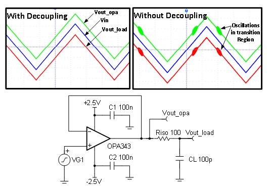
Figure 1: Buffer with and without decoupling (measured results)
Figure 2 illustrates why decoupling is important. Note that the inductance of the power supply trace will limit the transient current.
The decoupling capacitor is very close to the device, so it has a very low inductance path for current flow. During transients, the capacitor can supply very large amounts of current to the device for a very short duration.
The device without decoupling does not have a mechanism to provide the transient currents, so the amplifier’s internal nodes will droop – often referred to as a glitch. The internal power supply glitches on the device without decoupling cause inconsistent operation, because the internal nodes are not properly biased.
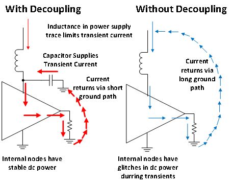
Figure 2: Current flow with and without decoupling
In addition to using a decoupling capacitor, you should also use a short low impedance connection between the decoupling capacitor, the power supply, and the ground connection.
Figure 3 compares a good decoupling layout to a bad one. You should always try to keep the decoupling connections short and avoid vias in the decoupling path, because vias add inductance. Most data sheets recommend a decoupling capacitor value. If no recommendation is given, use 0.1uF.
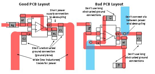
Figure 3: Good vs. bad PCB layout
Using a properly connected decoupling capacitor can save you a lot of trouble. Even if your circuit works on the bench without decoupling, it could have issues when you go into production from process variation and other real world influences.
Learn from my mistake; don’t fall into the no-decoupling trap!
A special thanks to my colleagues Ichiro Itoi and Tim Green for your insights into decoupling and real-world measured results.
-

Art Kay
-
Cancel
-
Vote Up
0
Vote Down
-
-
Sign in to reply
-
More
-
Cancel
Comment-

Art Kay
-
Cancel
-
Vote Up
0
Vote Down
-
-
Sign in to reply
-
More
-
Cancel
Children