

Part 2 of this blog series derived the basic transfer function for a typical 2-wire transmitter, commonly used in industrial control and automation, and explained the currents flowing inside it. It also explained that connecting the transmitter return (IRET) to the loop supply ground (GND) prevents proper operation of the transmitter.
Today’s post discusses the current consumption limits of the circuitry that is powered from the VREG and VREF outputs. Equation 1 and Figure 1 show that the output current (IO) equals the sum of the input current (IIN), the transmitter return current (IRET) and the BJT current (IBJT).

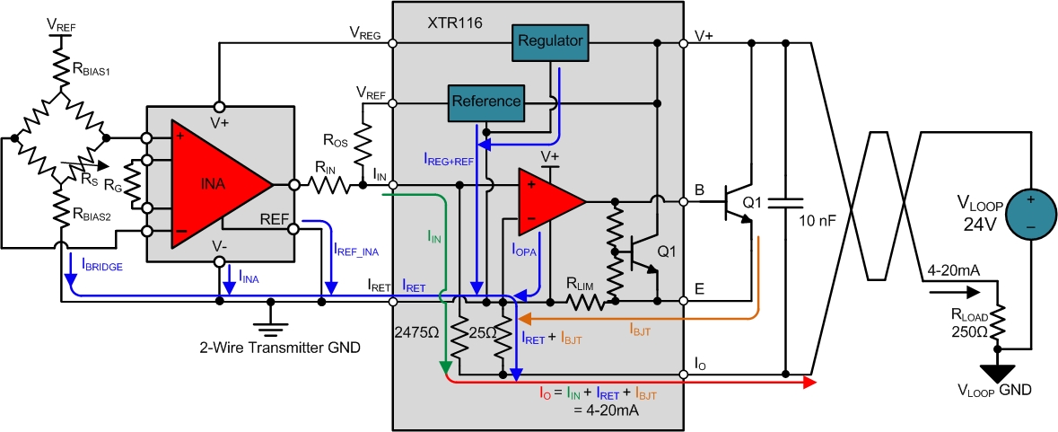
Figure 1: 2-wire transmitter showing current flow
IBJT and IIN will always be positive in this circuit configuration. Therefore, IRET currents that are greater than 4mA will prevent the U1 op amp from regulating the output current down to 4mA as required. The XTR116 quiescent current of 200uA flows through IRET, leaving roughly 3.8mA for the remaining circuitry powered from VREF and VREG. The output will not reach 4mA at the zero-scale input level if the external circuitry sinks more than 3.8mA to IRET.
Figure 2 shows the output current simulation results when the IBRIDGE, IINA and IREF_INA currents in Figure 1 total to 5.8mA. Notice that the output saturates at around 6mA, despite the input signal continuing to decrease. This results in an inability to properly convey the sensor information near the zero-scale levels.
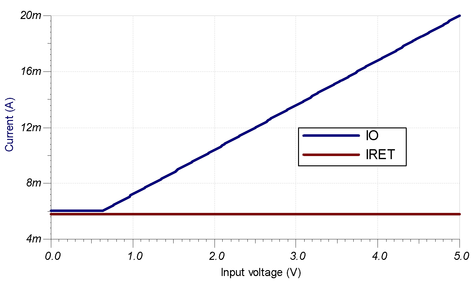
Figure 2: The effects of IRET current greater than 4mA
The use of low-resistance bridges is one of the most common causes for the IRET current to be greater than 4mA. Connecting a 120Ω strain gauge bridge to the 4.096V VREF output would require 34mA of current! Adding the RBIAS1 and RBIAS2 resistors to the circuit reduces the bridge current to an acceptable level, as shown in Figure 3.
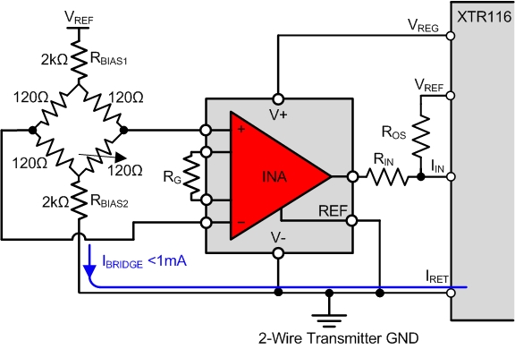
Figure 3: Using biasing resistors to reduce bridge currents
Equation 2 can be used to select the RBIAS resistor values based on a desired bridge current. The bridge current was set to roughly 1mA in this example to leave adequate current for other external circuitry.

The instrumentation amplifiers (INAs) and other external circuitry used in the design must use less than the remaining current available after powering the sensor. Table 1 lists a few low-voltage INAs with quiescent currents that make them suitable for 4-20mA systems.

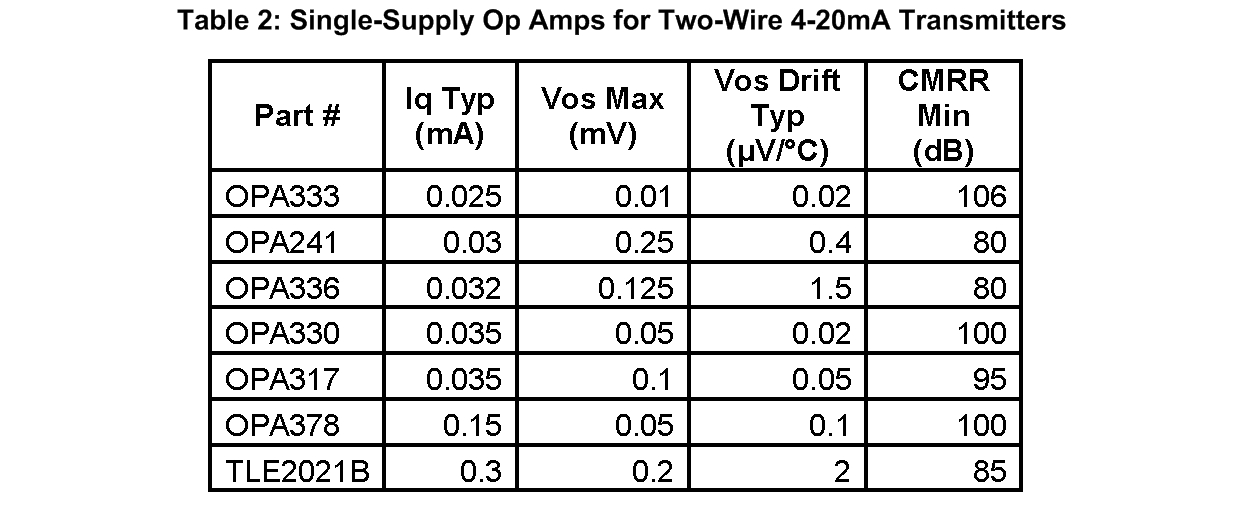
While the previous circuit examples have all used INAs, op amps are also commonly used to condition sensor signals in 2-wire transmitters. Table 2 lists op amps recommended for 2-wire transmitter circuits.
In summary, make sure the XTR and other circuitry powered from the loop regulators and references don’t exceed 4mA of operational current, or the output will saturate at low input levels. Be sure to use the active, and not just quiescent, currents of all components used in the design when determining the total current consumption. This is especially true with microcontrollers and other digital devices, which can consume considerably more current when active than inactive.
In my post next month on the Precision Hub we’ll talk about properly isolating and accepting pulse width modulated (PWM) inputs along with other digital input signals from devices not powered from the 2-wire loop circuitry.
Additional resources:
See related TI Designs reference designs for two-wire transmitters: TIPD126 and TIPD158.
See an overview of analog outputs and architectures from TI’s Kevin Duke.
Read about the evolution of 3-wire analog outputs.
See more posts in our 2-wire transmitters series.
-

user3650567
-
Cancel
-
Vote Up
0
Vote Down
-
-
Sign in to reply
-
More
-
Cancel
Comment-

user3650567
-
Cancel
-
Vote Up
0
Vote Down
-
-
Sign in to reply
-
More
-
Cancel
Children