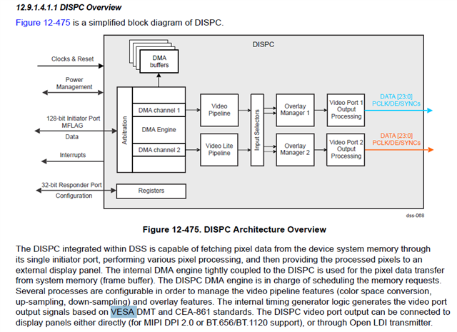
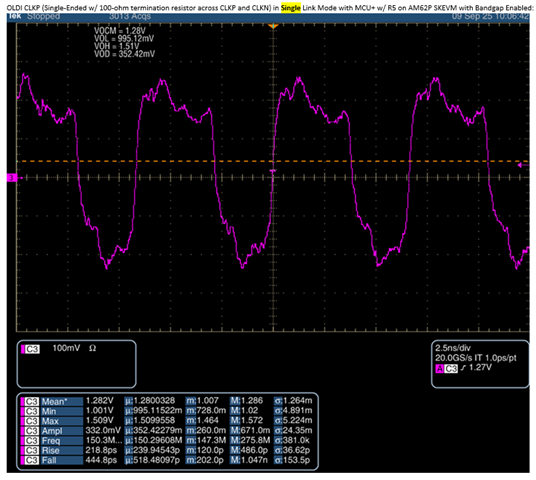
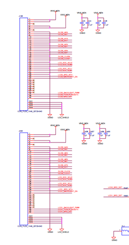
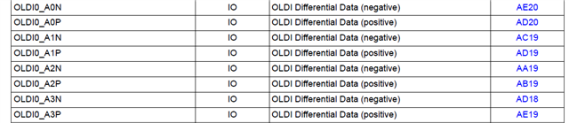
[FAQ] AM625 / AM623 / AM620-Q1 / AM625-Q1 / AM625SIP / AM62P / AM62P-Q1 Custom board hardware design – OLDI (Open LVDS Display Interface) capabilities

Other Parts Discussed in Thread: AM620-Q1, AM62P, AM625, SK-AM62P-LP

Hi TI Experts,

I have the below queries regarding the OLDI interface

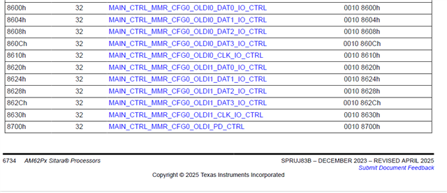
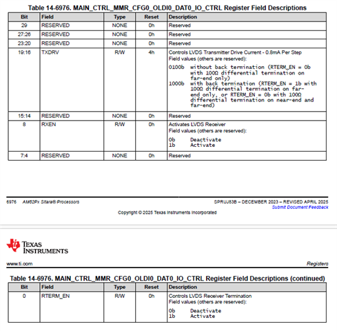
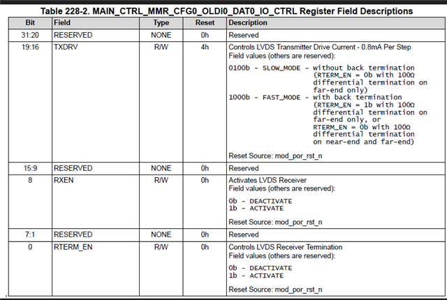
  1. Supported display configurations. Query regarding 8-lane, 4-lane and electrical compatibility.
  2. Is there a recommended part number that TI has tested?

Let me know your thoughts.

  • Hi Board designers, 

    Refer below inputs for the OLDI interface related queries.

    AM620-Q1 does not support OLDI interface.

    Supported display configurations.

    Does AM62xx support 4 lane or 8 lane or both 4/8 lane type of LCD displays.

    The AM62x/AM62Px OLDI support 1 X 8 lane (dual link mode) and 2 X 4 lane (single link )

     Query regarding 8-lane configuration.

    The LCD datasheet has segregated even and odd pairs on the data and clock lines. We would like to know if there are any recommendations for interfacing this type of LCD AM62xx

    In dual mode LCD configuration A0 through A3 correspond to the ODD pixels and A4 through A7 correspond to the even pairs. 

    Query regarding 4-lane configuration. 

    Is it possible to use 2 LVDS displays using 4-lanes for display-1 and another 4-lanes for display-2?

    AM62x

    It is possible to connect two displays and use the OLDI in single link mode. However, due to HW limitations, both the displays will be mirrored.

     If two displays, we used at the same time can I play two different videos are not?

    The videos will be duplicated. (Same video on both displays, mirror mode)

     AM62Px

    When OLDI0 interface is configured for x2 OLDI-SL display mode, the interface supports (can be configured)
    independent display streams (non-duplicate mode, non mirrored mode).

    Query related to electrical compatibility with the selected display.

    How to confirm the OLDI interface is compatible with the selected display?

    The OLDI LVDS electrical characteristics are summarized in the below table of the processor datasheet for comparison with the selected display.  

    7.8.7 OLDI LVDS (OLDI) Electrical Characteristics

     Help me understand the default data mapping of oLDI  VESA or JEIDA

    Refer below TRM section 

    12.9.1.4 DSS Functional Description
    12.9.1.4.1 DISPC Functional Description
    12.9.1.4.1.1 DISPC Overview

    Measurement of OLDI voltage and termination 

    Terminating and measuring OLDI waveform 

    (+) AM625: OLDI voltage swing and rise/fall time - Processors forum - Processors - TI E2E support forums

    https://e2e.ti.com/support/processors-group/processors/f/processors-forum/1273263/am625-oldi-voltage-swing-and-rise-fall-time/4836261?tisearch=e2e-sitesearch&keymatch=OLDI%20100#4836261

    lease refer to the below section of the data sheet

    7.11.5.17 OLDI
    7.11.5.17.1 OLDI0 Switching Characteristics
    Table 7-110 and Figure 7-94 present switching characteristics for OLDI0.
    Table 7-110. OLDI0 Switching Characteristics

    (1) Slow mode: TXDRV[3:0] = 0100b without back termination (RTERM_EN = 0b with 100Ω differential termination on far-end only)
    (2) Fast mode: TXDRV[3:0] = 1000b with back termination (RTERM_EN = 1b with 100Ω differential termination on far-end only, or
    RTERM_EN = 0b with 100Ω differential termination on near-end and far-end)

    Could you help me understand the setting you are using.

    Did you have a chance to measure the waveforms near to the SoC pins without the terminations connected to the OLDI display?

    The oldi register settings are the default values which corresponds to option 1(slow mode with 100 ohm differential termination on far end).

    We measured the oldi signals near the processor without termination,but they are not ok.

    With 100 ohms load at the LCD connector (without connecting LCD) we are seeing proper signals, which are meeting the DC specs as per processor datasheet

    How to disable OLDITX0 output if only using OLDITX1?

    OLDITX0 is the primary node, when only 4 channels are required OLDI0 should be used
    OLDITX0 and OLDITX1 can be enabled in clone mode. Same data will be available/transmitted on both the channels
    Also i understand that there is no hardware support to disable OLDITX0 and send data only on OLDITX1

    Do the differential signal pins (oLDI, USB, etc.) have the capabilities to adjust the swing of the voltage?

    No

    Recommended configuration when OLDI0 is not used 

    Refer to the Pin Connectivity table of the device specific data sheet.

    I would like to confirm that the bit ordering data[0 - 23] can modify depend on input VP format. Is it right?

    You could use CSC to change color component ordering, but otherwise, it is fixed. 

    I'd like you to tell more detail of CSC.AM62P has several CSCs in DSS (VID, VIDL1, VP1, VP2). Which can be used for this use case?

    Do you mean we can use CPR?

    CPR module in the Video port can be used to interchange the color position. 

    I got CPR module can be used to rotate color position.

    Could you please let me know that there are any requirements for configuration procedure of CPR?

    Its just 3x3 matrix, and can be configured at any point.


    AM625 display system capabilities

    Display subsystem
    – Dual display support
    – 1920x1080 @ 60fps for each display
    – 1x 2048x1080 + 1x 1280x720
    – Up to 165 MHz pixel clock support with
    Independent PLL for each display

    What do these numbers mean? For which display?

    On AM62x, we have two displays that could be driven independently. Both displays have independent PLLs and the independent PLLs allows users to connect two 1080p displays simultaneously with no restriction on FPS (VSYNC=60 Hz).

    The only impact to the system would be bandwidth. On AM62x, we only have 16bit DDR and if GPU or CPU were performing complex operations, they will not have enough bandwidth to get 60 FPS. The performance would vary based on the workload. Given the DDR limitations, we recommend customers to connect a 1920x1080 and 1280x720 screen for dual display to allow GPU and/or CPU to have bandwidth for their respective workload. 

    Resolution 2048x1080 for which display? LVDS in dual-channel mode? In the datasheet, it is mentioned 1x 2048x1080 + 1x 1280x720 resolution. Why?

    Both interfaces support upto 165MHz and it's up to the customer to chose the interface. In general, LVDS supports higher resolution panels like (1920x1200 or 2048x1080 or 1280x720) and DPI supports lower resolution panels.

    Recommended/ tested OLDI display 

    OLDI LCD with Capacitive Touch for AM62x Starter Kit EVM

    https://www.ti.com/tool/SK-LCD1

    https://e2e.ti.com/support/processors-group/processors/f/processors-forum/1257150/sk-am62a-lp-lvds-support-for-am62a-evk-and-am62x-evk

    References

    High-Speed Layout Guidelines for Reducing EMI for LVDS SerDes Designs

    https://www.ti.com/lit/pdf/snla302

    AN-1108 Channel-Link PCB and Interconnect Design-In Guidelines (Rev. A)

    https://www.ti.com/lit/pdf/snla008

    Display interface and functioning related threads for reference.

    https://www.forlinx.net/company-news/video-demo-of-ok6254-sbc-425.html

    (24) AM625: Interfacing LCD to AM625x - Processors forum - Processors - TI E2E support forums

    (24) SK-AM62: Recommended LCD panel for J21 - Processors forum - Processors - TI E2E support forums

    (25) AM625: DSS (Display Subsystem) of AM62x - Processors forum - Processors - TI E2E support forums

    (29) AM625: AM625 display system capabilities - Processors forum - Processors - TI E2E support forums

    Regards,

    Sreenivasa

  • Hi Board designers, 

    Refer below FAQ for OLDI impedance.

    https://e2e.ti.com/support/processors-group/processors/f/processors-forum/1329009/am625-oldi-interface-impedance

    These are the configurations for slow and fast mode

    (1) Slow mode: TXDRV[3:0] = 0100b without back termination (RTERM_EN = 0b with 100Ω differential termination on far-end only)
    (2) Fast mode: TXDRV[3:0] = 1000b with back termination (RTERM_EN = 1b with 100Ω differential termination on far-end only, or

    This is the case where internal back termination is off and external termination on the board is placed.
    RTERM_EN = 0b with 100Ω differential termination on near-end and far-end) 

    The far end termination may be inside or outside  and that depends on the attach device.

    Regards,

    Sreenivasa

  • Hi Board designers, 

    AM620-Q1 does not support OLDI interface.

    Regards,

    Sreenivasa

  • Hi Board designers, 

    Have you reviewed the below application note which details about the Display subsystem on AM62P and also details about how to configure Single Link OLDI -Independent mode and cloned mode using Linux Device tree.

    AM62P DSS Overview

    https://www.ti.com/lit/an/sprads3/sprads3.pdf

    Regards,

    Sreenivasa

  • Hi Board designers,

    Inputs related to common mode voltage.

    (+) SK-AM62P-LP: LVDS single link with DSS managed by WKUP_R5FSS0 - Processors forum - Processors - TI E2E support forums

    SK-AM62P-LP: LVDS single link with DSS managed by WKUP_R5FSS0

    I need to manage a single link LVDS display (4 lanes + clock) from the wakeup R5.

    The issue is that when switching to single link (from the syscfg), the LVDS common mode voltage drops to 0.6V

    Changing under "OLDI configration" the "Dual Mode" to enable, the LVDS common mode voltage is (as expected) 1.2V.

    We have found the issue. It turns our the MCU+ DSS driver for OLDI bridge was missing to enable the 1.2V IO bandgap reference for the OLDI single link mapper configuration. After enabling this, I am now able to see Vocm of ~1.2V. A patch will be provided shortly by Divyansh for you to try on your end.


    OLDI CLKP (Single-Ended w/ 100-ohm termination resistor across CLKP and CLKN) in Single Link Mode with MCU+ w/ R5 on AM62P SKEVM with Bandgap Enabled:

     Regards,

    Sreenivasa

  • Hi Board designers,

    Refer AM62P for OLDI MMR register description.

    Regards,

    Sreenivasa